Trailing edge variable camber wing driven by piezoelectric fiber materials

A piezoelectric fiber and trailing edge technology, applied in the field of trailing edge variable camber wings, can solve problems such as easy jamming, limited technology application and development, and slow drive speed, so as to reduce the weight of the wing structure and improve task adaptability performance, and the effect of improving stall characteristics

Active Publication Date: 2020-06-05
DALIAN UNIV OF TECH
View PDF6 Cites 13 Cited by
  • Summary
  • Abstract
  • Description
  • Claims
  • Application Information

AI Technical Summary

Problems solved by technology

At the current stage, although researchers at home and abroad have carried out a lot of research on wing deformation technology, there are still some problems that limit the application and development of this technology.
For example, in the mission adaptive wing project in the United States, an adaptive variable camber structure with multi-joints was designed for the F-111 aircraft, and a traditional hydraulic drive was used to drive the camber of the wing to change, but in the end due to the complex deformation structure, the weight loss was large and other reasons stopped further research on the project
Relevant researchers from Nanjing University of Aeronautics and Astronautics and Northwestern Polytechnical University have successively designed multi-articulated variable camber adaptive wings driven by multiple stepping motors, which also have the disadvantages of complex structure and easy jamming. The aerodynamic gain does not even offset the weight loss due to the addition of deformable structures
In addition to traditional drive mechanisms such as motors and hydraulics, intelligent material drives such as aerodynamic muscles, shape memory alloys, and ultrasonic motors are also widely used in the design of deformable wings, but there are corresponding limitations, such as the drive of shape memory alloys. The rate is slow, it is difficult to achieve fast and accurate tracking of wing deformation commands
The control accuracy of pneumatic muscles is average, and there is hysteresis effect

Method used


Image

  • Trailing edge variable camber wing driven by piezoelectric fiber materials
  • Trailing edge variable camber wing driven by piezoelectric fiber materials
  • Trailing edge variable camber wing driven by piezoelectric fiber materials

Examples


Embodiment Construction

[0022] In order to make the purpose, technical solutions and advantages of the embodiments of the present invention clearer, the technical solutions in the embodiments of the present invention will be clearly and completely described below in conjunction with the drawings in the embodiments of the present invention. Obviously, the described embodiments It is a part of embodiments of the present invention, but not all embodiments. Based on the embodiments of the present invention, all other embodiments obtained by persons of ordinary skill in the art without making creative efforts belong to the protection scope of the present invention.

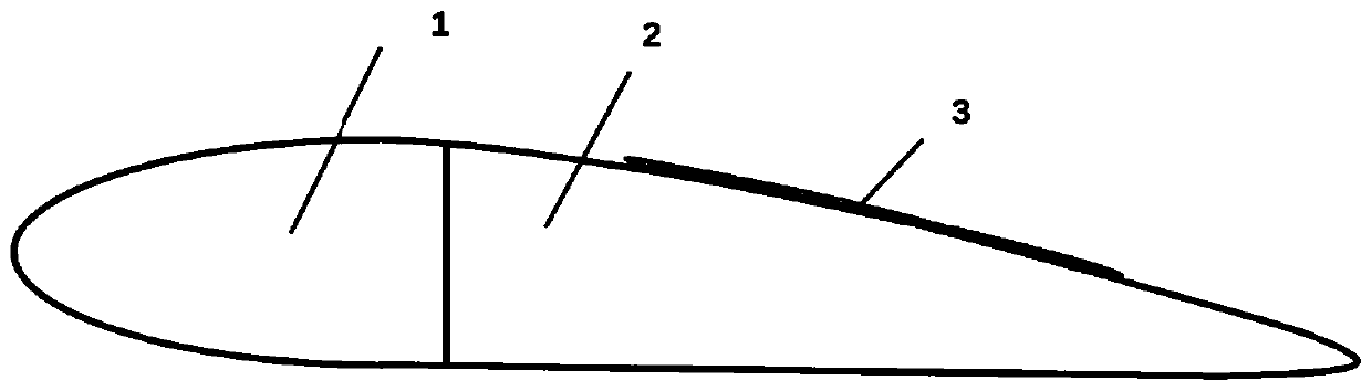
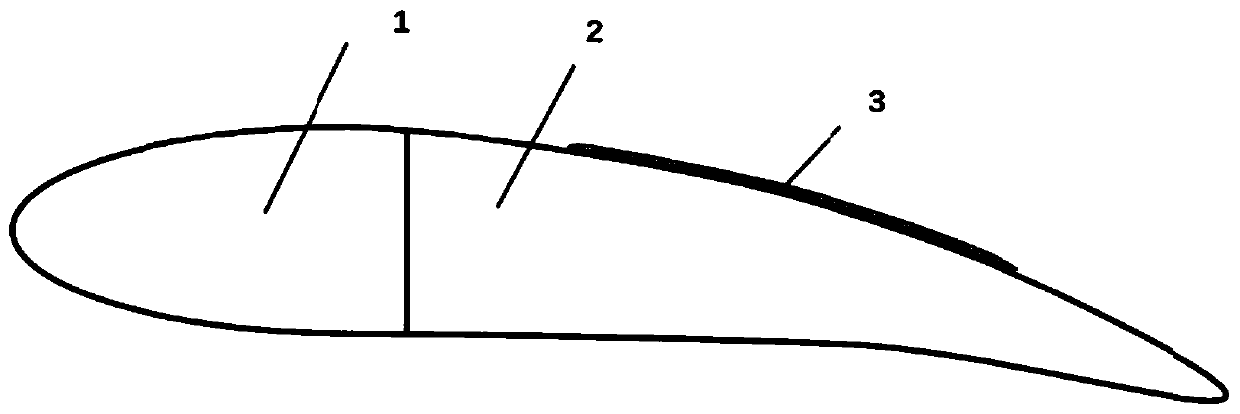
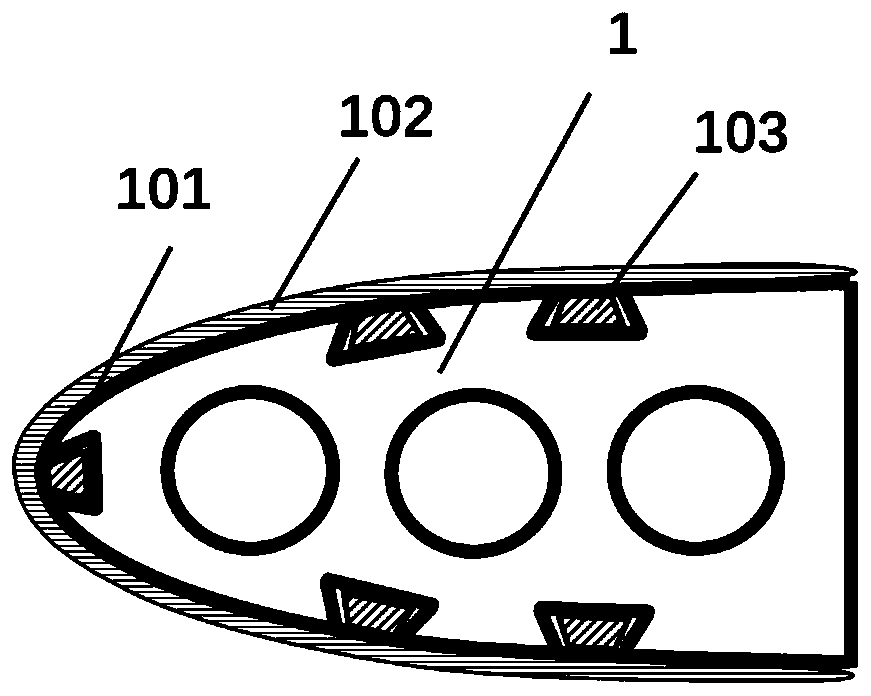
[0023] like figure 1 As shown, the embodiment of the present invention discloses a trailing edge variable camber wing driven by a piezoelectric fiber material, which consists of a fixed leading edge segment 1 with a constant camber, a flexible trailing edge deformable segment 2 with a variable camber, and an airfoil for adjusting The trailin...


PUM


Abstract

The invention provides a trailing edge variable camber wing driven by piezoelectric fiber materials. The wing comprises a leading edge fixing section with the invariable camber, a trailing edge flexible deformation section with the variable camber and a piezoelectric fiber composite material driver used for adjusting the change degree of the trailing edge flexible deformation section. The trailingedge flexible deformation section comprises a flexible wing rib, a stringer, a deformation skin, a segmented deformation skin and a segmented deformation skin fixing device. Voltage excitation is applied to the piezoelectric fiber composite material drivers, generated torque is transmitted to the flexible wing rib structure through the skin, and continuous and smooth change of the shape of the trailing edge of the wing is achieved. The wing structure mass can be greatly reduced, noise is reduced, the stealth characteristic is improved, the corresponding deformation control system is combined,accurate control over wing camber changes in the flight process can be achieved, the maneuvering and stall characteristics of an airplane are improved, and the task adaptability of the airplane is greatly enhanced.

Description

technical field [0001] The invention relates to the technical field of aviation products, in particular to a trailing edge variable camber wing driven by a piezoelectric fiber material. Background technique [0002] With the continuous improvement of aircraft performance requirements in the military and civilian fields, traditional wings have bottlenecks in improving aircraft mission adaptability and improving aircraft aerodynamic efficiency, and it is urgent to explore effective and feasible solutions. Wing deformation technology provides a new method and new idea for improving the mission adaptability of aircraft. [0003] The concept of morphing wing design has been around for a long time. In 1903, the first airplane of the Wright brothers realized the control of the flight state by twisting and deforming the wings. In 1920, Parker proposed the concept of variable camber wing design combining mechanical motion and compliance structure. Since the 1980s, active wing defo...

Claims


Application Information

Patent Timeline
Patent Type & Authority Applications(China)
IPC IPC(8): B64C3/44
CPCB64C3/44
Inventor 周文雅张宗宇王冠珺李阳胡欣涵牟泽辉王泽霖吕维梁
Owner DALIAN UNIV OF TECH
Why Eureka
Try Eureka