Road safety isolation fence for sponge city construction

A technology of sponge city and isolation fence, which is applied in road safety devices, roads, roads, etc., and can solve the problems of low safety performance of isolation fences and inability to accumulate rainwater, etc.

Inactive Publication Date: 2020-06-05
李泽蒙
View PDF10 Cites 12 Cited by
  • Summary
  • Abstract
  • Description
  • Claims
  • Application Information

AI Technical Summary

Problems solved by technology

[0005] The object of the present invention is to provide a road safety barrier for the construction of a sponge city with high safety performance an

Method used


Image

  • Road safety isolation fence for sponge city construction
  • Road safety isolation fence for sponge city construction

Examples


Embodiment 1

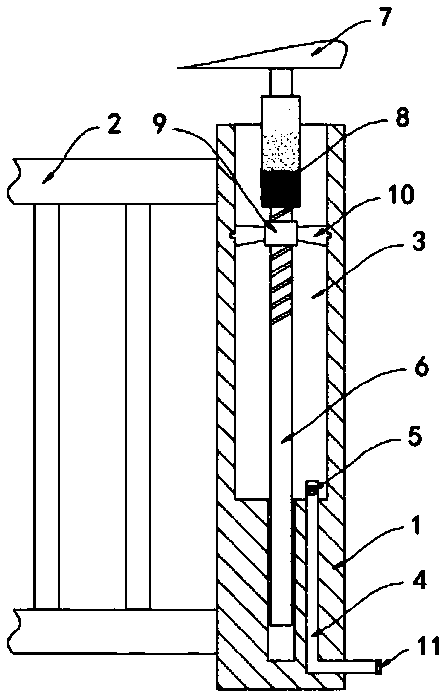
[0018] Such as figure 1 Shown, a kind of sponge city construction uses the road safety barrier, comprises the railing frame 1 that is vertically fixed on the ground, and the top of the railing frame 1 is provided with the handrail 2 that extends horizontally along the road, is provided with the water storage tank in the railing frame 1 3. The bottom of the water storage tank 3 is provided with an L-shaped water inlet pipe 4 extending to the bottom of the railing frame 1. The L-shaped water inlet pipe 4 is provided with a one-way valve 5, and the one-way valve 5 only allows rainwater outside the railing frame 1 to enter the water storage tank 3, the bottom port of the L-shaped water inlet pipe 4 is fixedly equipped with a filter screen 11 to prevent debris carried in the rainwater from entering the L-shaped water inlet pipe 4 and causing blockage.

[0019] The water storage tank 3 is provided with a movable rod 6 extending along its axial direction. The lower end of the movable...

Embodiment 2

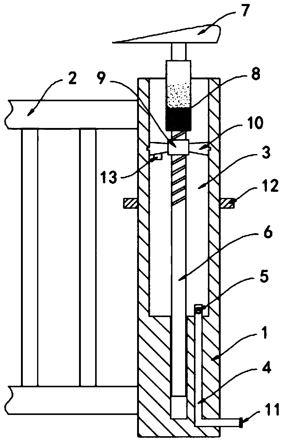
[0024] Such as figure 2 As shown, the difference between this embodiment and Embodiment 1 is that a dust removal ring 12 is movably sleeved on the side wall of the railing frame 1, and the dust removal ring 12 is composed of two half-ring magnets with opposite magnetic poles, and the fan blade 10 is fixed A permanent magnet block 13 is connected.

[0025] In this embodiment, when the fan blade 10 rotates, the permanent magnet block 13 is driven to rotate, and the permanent magnet block 13 periodically approaches or moves away from the half-ring magnets with opposite magnetic poles in the dust removal ring 12, that is, the dust removal ring 12 is generated periodically. The changing attractive and repulsive forces drive the dust removal ring 12 to reciprocate and slide up and down outside the railing frame 1 to scrape off the dust attached to the surface of the railing frame 1, thereby achieving a good dust removal effect.


PUM


Abstract

The invention belongs to the field of sponge cities, and in particular to a road safety isolation fence for sponge city construction. The isolation fence comprises a guardrail frame vertically fixed on the ground, a handrail horizontally extending along the road is arranged above the handrail frame; a water storage tank is arranged in the railing frame; an L-shaped water inlet pipe extending to the bottom of the railing frame is arranged at the bottom of the water storage tank; a one-way valve is arranged in the L-shaped water inlet pipe, a movable rod extending in the axis direction of the water storage tank is arranged in the water storage tank, the lower end of the movable rod extends into the handrail frame and is in sliding connection with the handrail frame, and the upper end of themovable rod extends out of the water storage tank and is fixedly connected with a horizontally-arranged wing plate. The movable rods can be driven by the wing plates to move upwards, a driver can judge the approximate vehicle speed at the moment by observing the colors on the tubular reflecting plates, guarantee is provided for road safety, rainwater can be sucked into the water storage tank to bestored in a rainy day environment, and the concept of sponge city construction is met.

Description

technical field [0001] The invention belongs to the field of sponge cities, and in particular relates to a road safety isolation barrier for sponge city construction. Background technique [0002] Road barriers are a kind of basic traffic facilities, in order to isolate roads of different nature and directions from each other, so as to ensure that the roads do not interfere with each other, so as to ensure traffic safety. [0003] The structure of the traditional road barrier is fixed, which can only isolate the traffic flow and ensure that the roads do not interfere with each other. When the vehicles on the road are fast, the barrier cannot serve as a warning, so the safety performance is low, and With the acceleration of the construction of sponge cities, the existing barriers cannot collect rainwater and cool down the city, and have a single function. [0004] To this end, we propose a road safety barrier for sponge city construction to solve the above problems. Conten...

Claims


Application Information

Patent Timeline
IPC IPC(8): E01F15/02E01F9/619E01F9/669E03B3/02E03B11/00B08B1/00
CPCB08B1/005B08B1/008E01F15/02E03B3/02E03B11/00E01F9/619E01F9/669Y02A20/108
Inventor 李泽蒙范金婷
Owner 李泽蒙
Why Eureka
Try Eureka