
A solar-powered automatic snow removal device for a dome of a house

A solar power supply and solar panel technology, which is applied to water supply devices, circuit devices, drinking water devices, etc., can solve the problems of low intelligence and ineffective use of snow, and achieve improved intelligence, various snow removal methods, and controllable effect of science

Active Publication Date: 2021-01-26
HUNAN UNIV OF ARTS & SCI
View PDF1 Cites 0 Cited by
  • Summary
  • Abstract
  • Description
  • Claims
  • Application Information

AI Technical Summary

Problems solved by technology

[0004] The purpose of the present invention is to provide a solar-powered automatic snow removal device for house domes to solve the problems of low intelligence and no effective use of snow in the above-mentioned background technology

Method used


Image

  • A solar-powered automatic snow removal device for a dome of a house
  • A solar-powered automatic snow removal device for a dome of a house
  • A solar-powered automatic snow removal device for a dome of a house

Examples


Embodiment 1

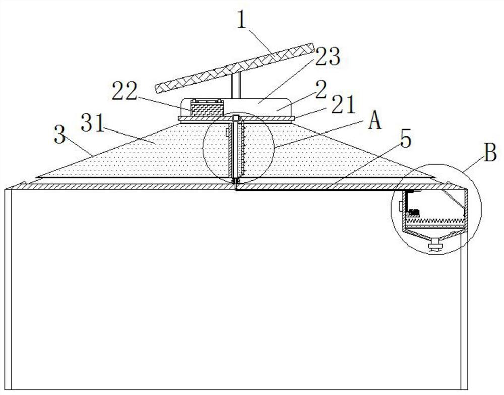
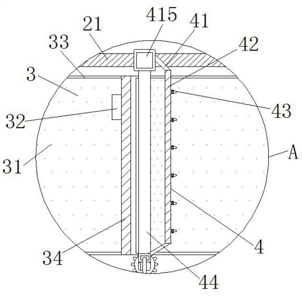
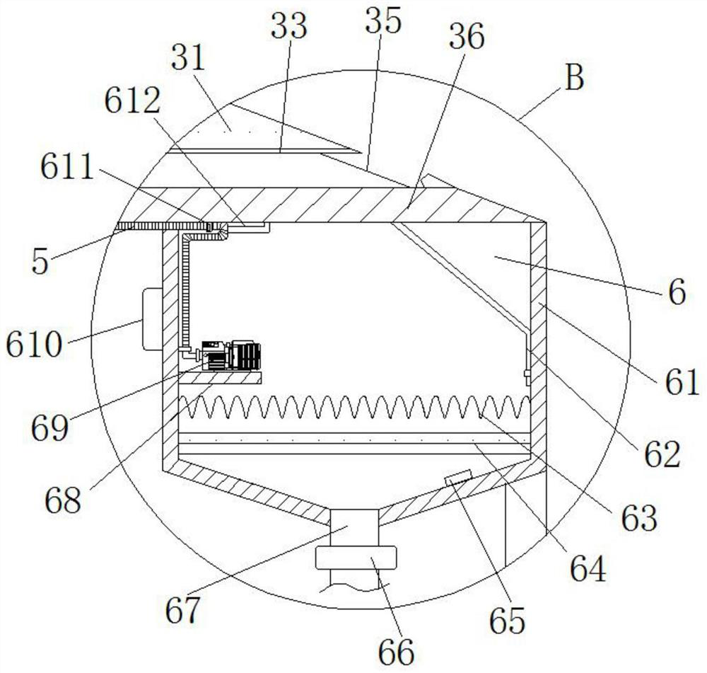
[0026]Embodiment 1: A solar-powered automatic snow removal device for a dome of a house, comprising a solar panel 1. An energy storage structure 2 is fixedly installed at the bottom end of the solar panel 1. The energy storage structure 2 includes an electromagnetic slide rail 21, a battery 22, and a roof 23 and the fixed rod 24. The top view of the fixed rod 24 is a circular structure, and the fixed rod 24 is used in conjunction with the electromagnetic slider 415. The battery 22 is installed inside the roof 23, and the electromagnetic slider 415 can be mounted on the electromagnetic slide rail 21. The surface slides on the fixed block 47, so that the first rotating shaft 44 is always parallel to the surface of the transparent film 31. The surface of the roof 23 on the energy storage structure 2 is connected with the electromagnetic slide rail 21 through the fixed rod 24 to store energy A roof structure 3 is fixedly connected to the bottom end of the structure 2.

[0027]The roof stru...

Embodiment 2

[0030]Embodiment 2: A solar-powered automatic snow removal device for a dome of a house, comprising a solar panel 1, characterized in that an energy storage structure 2 is fixedly installed at the bottom end of the solar panel 1, and the energy storage structure 2 includes an electromagnetic slide 21 and a battery 22. The roof 23 and the fixed rod 24. The top view of the fixed rod 24 is a circular structure, and the fixed rod 24 is used in conjunction with the electromagnetic slider 415. The battery 22 is installed inside the roof 23, and the electromagnetic slider 415 can The surface of the electromagnetic slide rail 21 slides and is used in conjunction with the fixed block 47, so that the first rotating shaft 44 is always parallel to the surface of the transparent film 31, and the squeegee 42 is parallel to the surface of the transparent film 31, which is convenient for the squeegee 42 to scrape the product. Snow, the surface of the house roof 23 on the energy storage structure 2 ...


PUM


Abstract

The invention discloses a solar-powered automatic snow removal device for a dome of a house, which includes a solar panel, an energy storage structure is fixedly installed at the bottom of the solar panel, and an electromagnetic slide is connected to the roof surface of the energy storage structure through a fixing rod. The bottom end of the energy storage structure is fixedly connected to the roof structure, and one side of the transparent film on the roof structure is fixedly connected to the first connecting rod, and the left side of the first connecting rod is fixedly connected to the pressure sensor. The surface of the structure is provided with a moving device, and the bottom end of the second connecting rod on the moving device is fixed with a scraper. The invention is equipped with a roof structure and a moving device, which greatly improves the intelligence of the device, has various snow removal methods, can start snow removal in time, and avoids damage to the roof, and can effectively utilize snow melt water through the melt water utilization device, Avoid melting water to form ice cones and ensure the safety of pedestrians.

Description

Technical field[0001]The invention relates to the technical field of snow removal devices, in particular to a solar-powered automatic snow removal device for domes of houses.Background technique[0002]With the continuous development of society, when dome houses encounter heavy snowfall in winter, a lot of snow will accumulate on the roof. Under normal circumstances, the steel roof is higher than the ground and has a large area, and the surface is slippery during snowfall. Therefore, manual snow removal is unsafe and inefficient, and cannot meet the requirements. It also brings the following hazards: First, under the pressure of a large amount of snow, the roof is prone to collapse, resulting in house damage and casualties. Secondly, for low-rise houses, as the temperature rises, a large amount of snow will slowly melt, and the melted water is easy to freeze at the eaves and form ice cones, resulting in accidents of falling ice cones. In order to avoid the above hazards, People usuall...

Claims


Application Information

Patent Timeline
Patent Type & Authority Patents(China)
IPC IPC(8): E04D13/10E03B3/30E04D13/18H02S20/23H02J7/35
CPCE03B3/30E04D13/10E04D13/103H02J7/35H02S20/23Y02B10/10Y02E10/50
Inventor 杨莹刘涛肖黎陈豪高祺哲
Owner HUNAN UNIV OF ARTS & SCI
Learn More