Method for preparing liquid suction core in pressure sintering method

A pressurized sintering and liquid-absorbing core technology, applied in lighting and heating equipment, indirect heat exchangers, etc., can solve the problems of uneven porosity and shrinkage during sintering, and achieve the goal of improving the uniformity of porosity and avoiding shrinkage Effect

Active Publication Date: 2020-06-05
南京宇源新能碳中和科技有限公司
View PDF5 Cites 0 Cited by
  • Summary
  • Abstract
  • Description
  • Claims
  • Application Information

AI Technical Summary

Problems solved by technology

[0005] The purpose of the present invention is to provide a preparation method of a liquid-absorbent core to solve the problems of serious shrinkage and uneven porosity in the sintering process in the prior art. The present invention combines continuous powder addition, induction heating, and pressure sintering Ways to prepare wicks

Method used


Image

  • Method for preparing liquid suction core in pressure sintering method

Examples


Embodiment 1

[0021] The metal tube shell is made of 18*3 metal titanium tube; the metal layer (1) is made of porous stainless steel with a pore diameter of

[0022] 13μm, the porosity is 65%. The metal powder is nickel powder with a particle size of 2 μm.

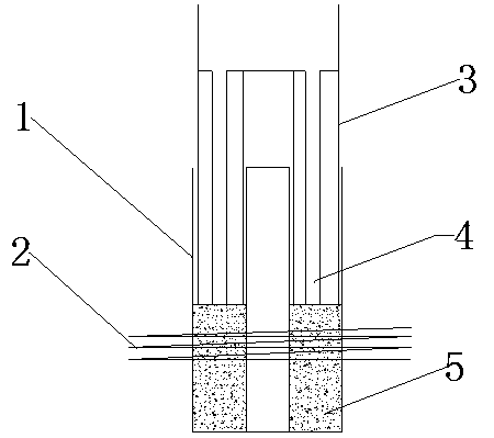
[0023] Such as figure 1 As shown, the porous stainless steel is inserted into the titanium tube with the lower end fixed. Nickel powder from the feeding device

[0024] Pour from above, set the motion period of the feeding device to 1 s, the pressing pressure of the feeding device on the metal powder is 2 MPa, and the frequency of the induction coil is 1000 HZ.

[0025] The moving speed of the titanium tube is 0.2 cm / s. To be sintered with nickel powder between the titanium tube and the porous stainless steel

[0026] After the liquid-absorbent core, stop each equipment, and the preparation of the liquid-absorbent core can be completed.

Embodiment 2

[0028] 22*3 metal copper pipes are selected for the metal shell; porous stainless steel is selected for the metal layer (1), and the aperture is

[0029] 20μm, the porosity is 55%. The metal powder is nickel powder with a particle size of 5 μm.

[0030] Such as figure 1 As shown, the porous stainless steel is inserted into the copper tube, and the lower end is fixed. Nickel powder from the feeding device

[0031] Pour from above, set the motion cycle of the feeding device to 2 s, the pressing pressure of the feeding device on the metal powder is 3 MPa, and the frequency of the induction coil is 2000 HZ.

[0032] The moving speed of the titanium tube is 0.1 cm / s. After the copper tube and the porous stainless steel are filled with copper powder and sintered

[0033] After the liquid-absorbent core, stop each equipment, and the preparation of the liquid-absorbent core can be completed.

Embodiment 3

[0035] The metal tube shell is made of 16*1 metal copper tube; the metal layer (1) is made of porous copper, and the aperture is

[0036] 15μm, the porosity is 55%. The metal powder is copper powder with a particle size of 1 μm.

[0037] Such as figure 1 As shown, the porous copper is inserted into the copper pipe, and the lower end is fixed. Copper powder from the feeding device

[0038] Pour from above, set the motion period of the feeding device to 3 s, the pressing pressure of the feeding device on the metal powder is 1 MPa, and the frequency of the induction coil is 1500 HZ.

[0039] The moving speed of the titanium tube is 0.4 cm / s. The suction liquid that is filled with copper powder and sintered between the copper tube and the porous copper

[0040] After the core is finished, all equipment is stopped to complete the preparation of the liquid-absorbent core.


PUM

PropertyMeasurementUnit
pore sizeaaaaaaaaaa
particle diameteraaaaaaaaaa
pore sizeaaaaaaaaaa

Abstract

The invention discloses a method for preparing a liquid suction core in a pressure sintering method. The liquid suction core is composed of a metal pipe shell, capillary pipes (1) and capillary pipes(2). The capillary pipes (1) are inserted in the metal pipe shell to form cavities, a feeding device continuously feeds metal powder at an infinitesimal speed into the cavities and compacts the metalpowder through high-speed up-and-down reciprocating motion, the metal powder is sintered and formed through high-frequency induction heating, one-step preparation of the liquid suction core is achieved, and the whole process is finished under a vacuum condition. Pressure sintering and high-frequency induction are conducted at the same time, a contraction problem existing in the conventional sintering process can be solved, the capillary pipes (2) are tightly attached to the metal pipe shell, and the porosity uniformity of the capillary pipes (2) is effectively improved. In addition, the liquidsuction core is formed by assembling a metal outer pipe and a liquid suction core body in a conventional method, the requirements for the matching sizes of the metal outer pipe and the liquid suctioncore body are extremely high, and the problem can be solved through one-step sintering in the method.

Description

technical field [0001] The invention relates to a method for preparing a liquid-absorbing core by a pressurized sintering method, which can be applied to the fields of aviation thermal control and cooling of electronic equipment. Background technique [0002] Loop heat pipe is a high-efficiency two-phase thermal control technology. With its high-efficiency heat transfer rate, long-distance transmission, good isothermal performance, and flexible and convenient structural design, it has become the preferred choice in the field of heat exchange for aerospace and high-density electronic equipment. Cooling, heat recovery, and air-conditioning and refrigeration are increasingly being used. [0003] A typical heat pipe consists of a tube shell, a liquid-absorbing core and an end cap. The negative pressure in the tube is filled with an appropriate amount of working liquid, so that the capillary porous material of the liquid-absorbing core close to the inner wall of the tube is fille...

Claims


Application Information

Patent Timeline
Patent Type & Authority Applications(China)
IPC IPC(8): F28D15/04
CPCF28D15/046
Inventor 俞健杨佳辉沈芳洁
Owner 南京宇源新能碳中和科技有限公司
Why Eureka
Try Eureka