Scanning target fixing device

A technology of fixing device and target, which is applied in the field of laser scanning to achieve the effect of not easy to block and high height

Pending Publication Date: 2020-06-05
HUNAN LIANZHI BRIDGE & TUNNEL TECH
View PDF0 Cites 3 Cited by
  • Summary
  • Abstract
  • Description
  • Claims
  • Application Information

AI Technical Summary

Problems solved by technology

[0005] The purpose of the present invention is to provide a scanning target fixing device to solve the problem of erecting three-dimensional laser scanning targets in different environments

Method used


Image

  • Scanning target fixing device
  • Scanning target fixing device
  • Scanning target fixing device

Examples


Embodiment Construction

[0034] The embodiments of the present invention will be described in detail below with reference to the accompanying drawings, but the present invention can be implemented in various ways defined and covered by the claims.

[0035] see Figure 1 to Figure 4 , a scanning target fixing device, this embodiment is applied to three-dimensional laser scanning target fixing.

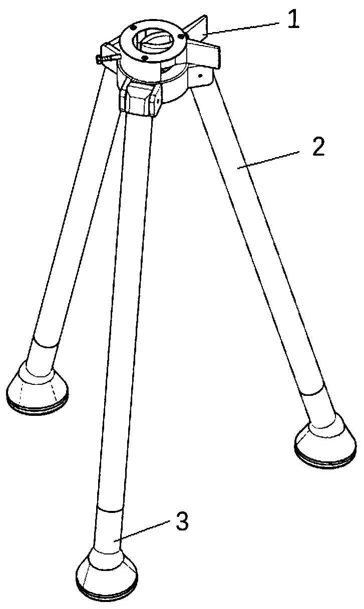
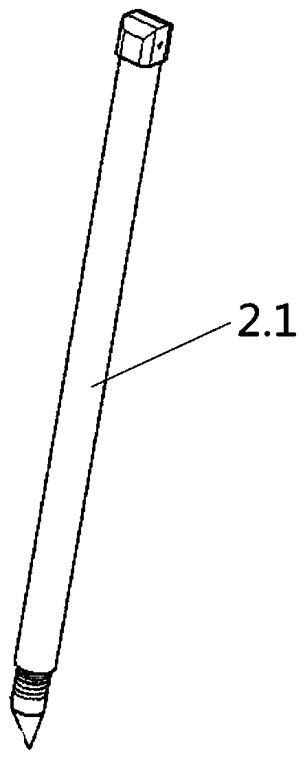
[0036] A scanning target fixing device, comprising a target fixing seat 1, a bracket rod group 2 and a bracket terminal 3; the bracket rod group 2 includes at least three bracket rods 2.1, and one end of a plurality of the bracket rods 2.1 is connected to the target fixing seat 1 is hinged, and the other end of the support rod 2.1 is provided with a support terminal 3; in this embodiment, the support rod group 2 is provided with three support rods 2.1.

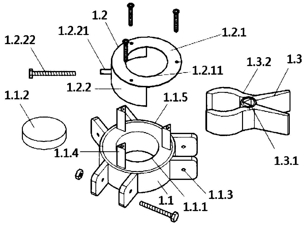
[0037] see figure 2 , the target fixing seat 1 includes a magnetic base 1.1 and a target fixing clamp 1.3; the target fixing clamp 1.3 is installed on the m...


PUM


Abstract

The invention provides a scanning target fixing device. The device comprises a target fixing base, a support rod set and support terminals. The support rod set comprises at least three support rods, wherein one end of each support rod is hinged to the target fixing base, and the other end of each support rod is provided with one support terminal; the target fixing base comprises a magnetic attraction base and a target fixing clamp; the target fixing clamp is installed on the magnetic attraction base and used for attracting, clamping and fixing a scanning target. The bottoms of the support terminals are provided with a magnetic attraction chassis capable of being attracted and fixed to the magnetic installation face, and the magnetic attraction chassis is used for erecting and installing the scanning target fixing device on a horizontal plane or a non-horizontal plane. According to the invention, the scanning target is fixed by the target fixing clamp and the magnetic attraction base, so the scanning target cannot fall off from the fixing device when being erected on a non-horizontal plane; by combining the support rods and the magnetic type support terminals, the problem that the three-dimensional laser scanning target is large in layout limitation is solved.

Description

technical field [0001] The invention relates to the technical field of laser scanning, in particular to a scanning target fixing device. Background technique [0002] The rapid development of 3D laser scanning technology has replaced many traditional single-point coordinate measurement methods due to its high-efficiency, non-contact and high-precision acquisition of multivariate data such as point cloud coordinates, color and reflectivity on the surface of the scanned object. The multi-station original point cloud data obtained by 3D laser scanning needs common features as stitching primitives during stitching and orientation, and the scanning target is the most commonly used common feature. Common scanning targets include spherical targets and black-and-white checkerboard-shaped planar targets, among which spherical targets are mostly plastic balls with good reflection, and black-and-white checkerboard-shaped planar targets are mostly metal sheets coated with various high-c...

Claims


Application Information

Patent Timeline
IPC IPC(8): G01C15/02G01B11/24
CPCG01B11/24G01C15/02
Inventor 梁晓东杨承昆刘春吴勇生
Owner HUNAN LIANZHI BRIDGE & TUNNEL TECH
Why Eureka
Try Eureka