Durability test device and method for water meter
A durability test and water meter technology, applied in the direction of testing/calibrating devices, measuring devices, testing/calibrating volume flow, etc., can solve the problems of large hardware loss and high test cost, and achieve the goal of improving efficiency, no loss, and saving manpower and material resources Effect
- Summary
- Abstract
- Description
- Claims
- Application Information
AI Technical Summary
Problems solved by technology
Method used
Image

Examples
Embodiment Construction
[0036] The technical solutions in the present invention are clearly and completely described below in combination with the accompanying drawings in the embodiments of the present invention. Obviously, the described embodiments are only some of the embodiments of the present invention, not all of them. Based on the embodiments of the present invention, all other embodiments obtained by persons of ordinary skill in the art without creative efforts fall within the protection scope of the present invention.
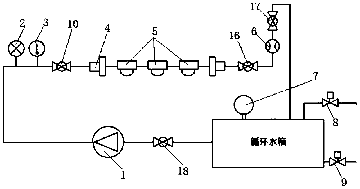
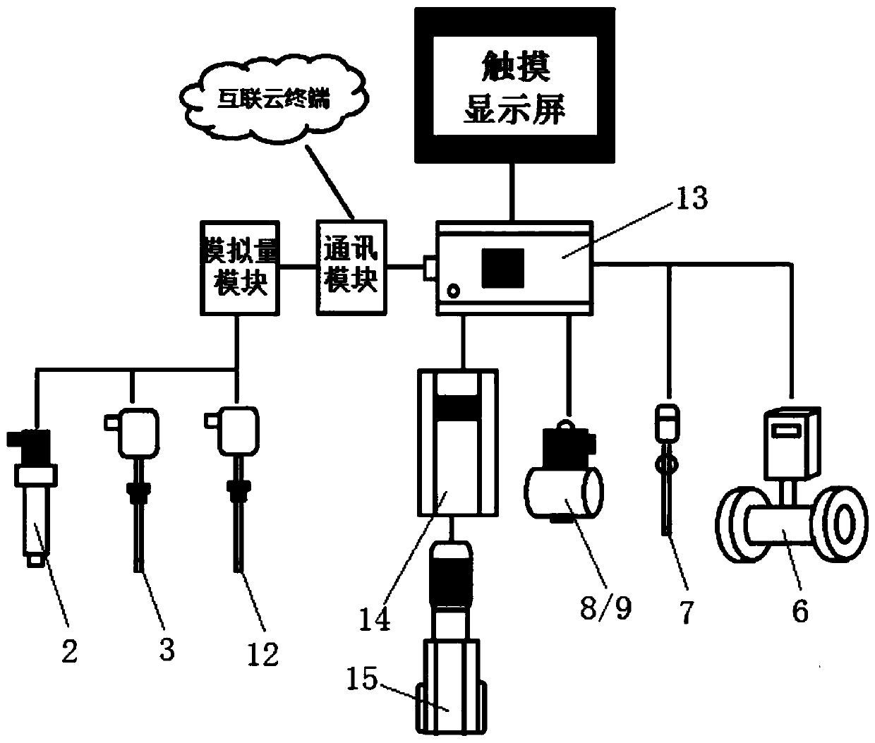
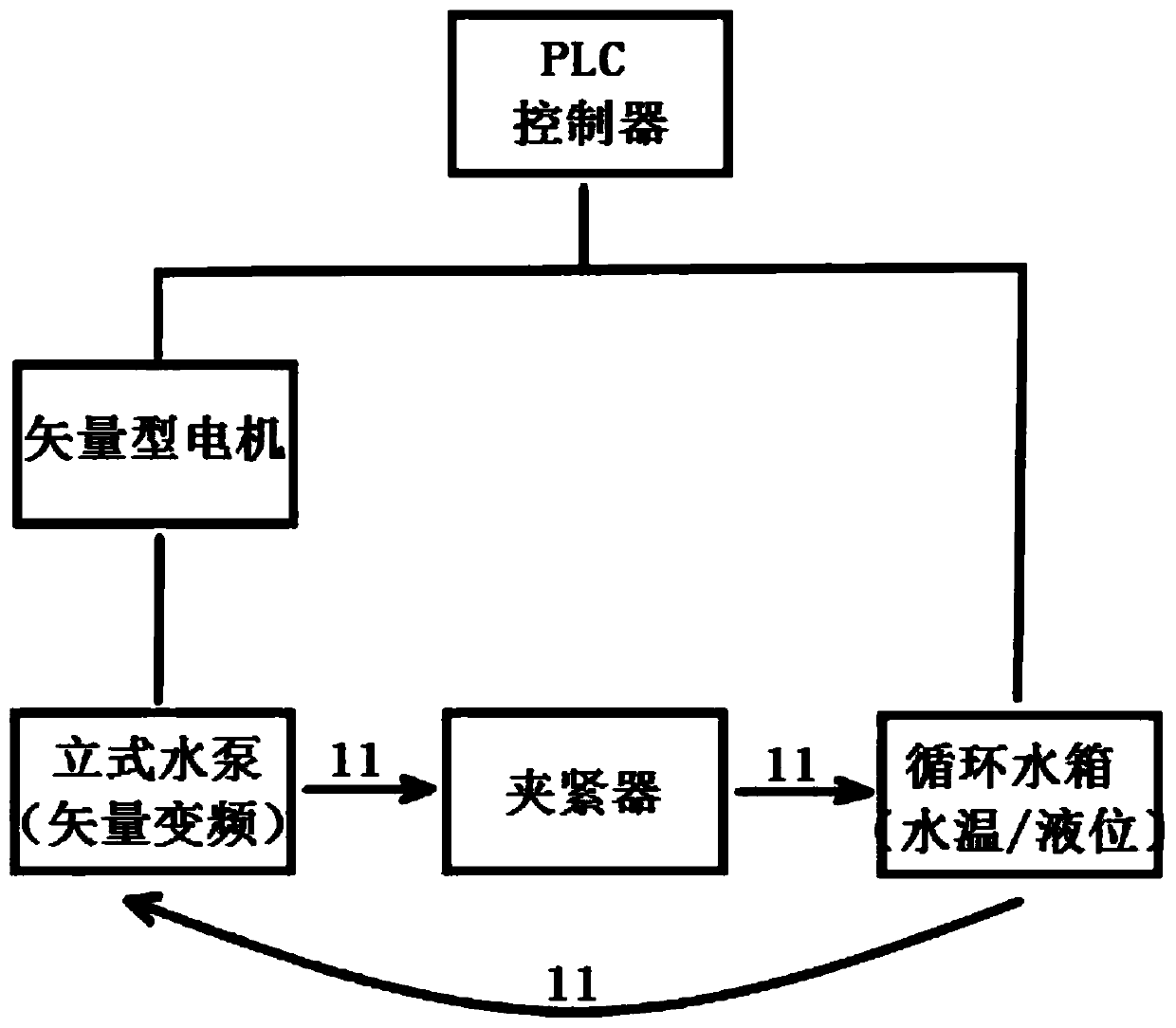
[0037] Such as figure 1 and 2 As shown, the durability test device of a water meter provided by the present invention includes: a circulating water tank, a vertical water pump 1, a flow meter 6, a PLC controller 13, a touch display screen, a meter clip 4, a constant torque frequency converter 14. Vector motor 15, first temperature sensor 3 and second temperature sensor 12, pressure sensor 2, and liquid level sensor 7;
[0038] The circulating water tank communicates with th...
PUM
 Abstract
Description
Claims
Application Information
 - Generate Ideas
- Intellectual Property
- Life Sciences
- Materials
- Tech Scout
- Unparalleled Data Quality
- Higher Quality Content
- 60% Fewer Hallucinations
Browse by: Latest US Patents, China's latest patents, Technical Efficacy Thesaurus, Application Domain, Technology Topic, Popular Technical Reports.
© 2025 PatSnap. All rights reserved.Legal|Privacy policy|Modern Slavery Act Transparency Statement|Sitemap|About US| Contact US: help@patsnap.com