Geographic information calibration method for strain tower in overhead transmission line

A technology for overhead transmission lines and calibration methods, which is applied in the field of geographical information calibration of tension towers in overhead transmission lines, can solve the problems that the disturbance position of the optical fiber sensing system cannot be mapped to the actual geographic coordinates, and the length of the tower optical cable does not match. To facilitate maintenance work, reduce the probability of misjudgment events, and increase reliability

Active Publication Date: 2020-06-05
NANJING FAAIBO OPTOELECTRONICS TECH +1
View PDF11 Cites 2 Cited by
  • Summary
  • Abstract
  • Description
  • Claims
  • Application Information

AI Technical Summary

Problems solved by technology

[0005] Purpose of the invention: In view of the above problems, the present invention discloses a geographical information calibration method of a tension tower in an overhead power transmission line. By synchronizing the working time of the optical fiber sensing equipment and the vibrator on the tension tower with a GPS device, the location of the vibration is judged. Position, it is very easy to calibrate the relationship between the geographical coordinates of the strain tower and the length of the optical cable to the optical port of the equipment, and calculate the GPS coordinates of the st

Method used


Image

  • Geographic information calibration method for strain tower in overhead transmission line
  • Geographic information calibration method for strain tower in overhead transmission line
  • Geographic information calibration method for strain tower in overhead transmission line

Examples


Embodiment Construction

[0035] The technical solutions of the present invention will be further described below in conjunction with the accompanying drawings and embodiments.

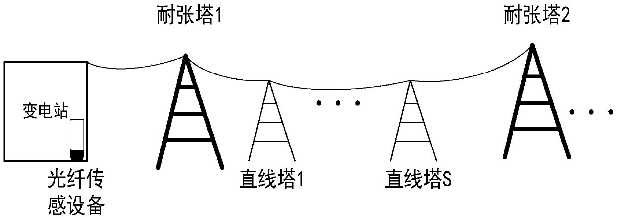
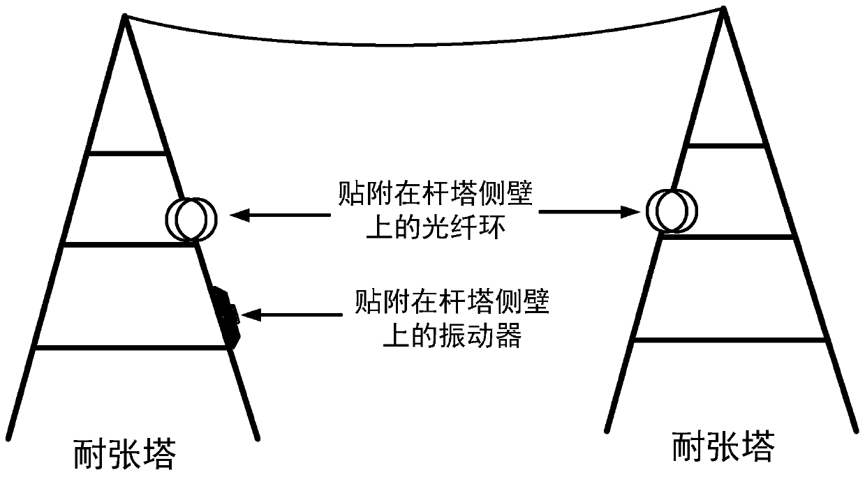
[0036]The present invention proposes a geographic information calibration method for tension towers in overhead power transmission lines based on vibration-sensitive optical fiber sensing technology. The working time of the optical fiber sensing system and the vibrator on the tension tower is synchronized through the GPS device, and the fiber optic cable is used to There is often a margin when connecting on a strain tower. For example, there will be an optical fiber ring attached to the side wall of the tower or an optical fiber splicing box attached to the side wall of the tower. Vibrator will apply a specific frequency to the side wall of the tower Vibration, this vibration is coupled to the optical fiber ring of the strain tower or the optical fiber in the optical fiber connection box, and the vibration event of this specifi...


PUM


Abstract

The invention discloses a geographic information calibration method for a strain tower in an overhead transmission line. A system for realizing the method comprises optical fiber sensing equipment sensitive to vibration, a low-power-consumption vibrator and a GPS device. According to the invention, the optical fiber sensing equipment sensitive to vibration is utilized; the working time of the optical fiber sensing equipment and the working time of the vibrator on the strain tower are synchronized through the GPS device; the position where vibration occurs is judged; the relationship between the geographical coordinates of the strain tower and the length of the optical cable from the strain tower to the optical port of the equipment can be easily calibrated; the GPS coordinates of the tangent towers between the strain towers and the length of the optical cable from the tangent towers to the optical port of the equipment are calculated through an interpolation method; the problem that adisturbance position detected by an optical fiber sensing system cannot be mapped to an actual geographical coordinate due to the fact that the sag of a power transmission cable and the span between towers are inconsistent with the distance of an optical cable is solved, the geographical position of a power transmission line accident is rapidly positioned, and maintenance work of related personnelis facilitated.

Description

technical field [0001] The invention belongs to the technical field of optical fiber sensing, and in particular relates to a geographical information calibration method of a strain tower in an overhead power transmission line. Background technique [0002] Cables in overhead transmission lines include not only cables for power transmission, but also optoelectronic composite cables such as OPGW (optical fiber composite overhead ground wire), OPLC (optical fiber composite low-voltage cable) or ADDS (all-dielectric self-supporting optical cable). The optical unit is responsible for the internal communication and data collection tasks of the power grid. There are generally two types of towers for power lines. The first is a straight tower, and the second is a strain tower. The function of a straight tower is to stir up the wires, and generally only bear the weight of the wires, that is, the vertical load. The load of the strain tower is much larger than that of the straight tow...

Claims


Application Information

Patent Timeline
IPC IPC(8): G01H9/00G01S19/42
CPCG01H9/004G01S19/42
Inventor 邹宁睦熊菲董秋豪张道方行赵随意李云飞
Owner NANJING FAAIBO OPTOELECTRONICS TECH
Why Eureka
Try Eureka