
Multi-dimensional domain joint SAR broadband interference suppression method based on low-rank matrix decomposition

A broadband interference and low-rank matrix technology, applied in the signal field, can solve problems such as signal energy loss, low rank, and interference signals that do not have low-rank characteristics, and achieve the effects of suppressing interference, improving image quality, and avoiding loss of useful signals

Active Publication Date: 2020-06-05
NORTHWESTERN POLYTECHNICAL UNIV
View PDF2 Cites 7 Cited by
  • Summary
  • Abstract
  • Description
  • Claims
  • Application Information

AI Technical Summary

Problems solved by technology

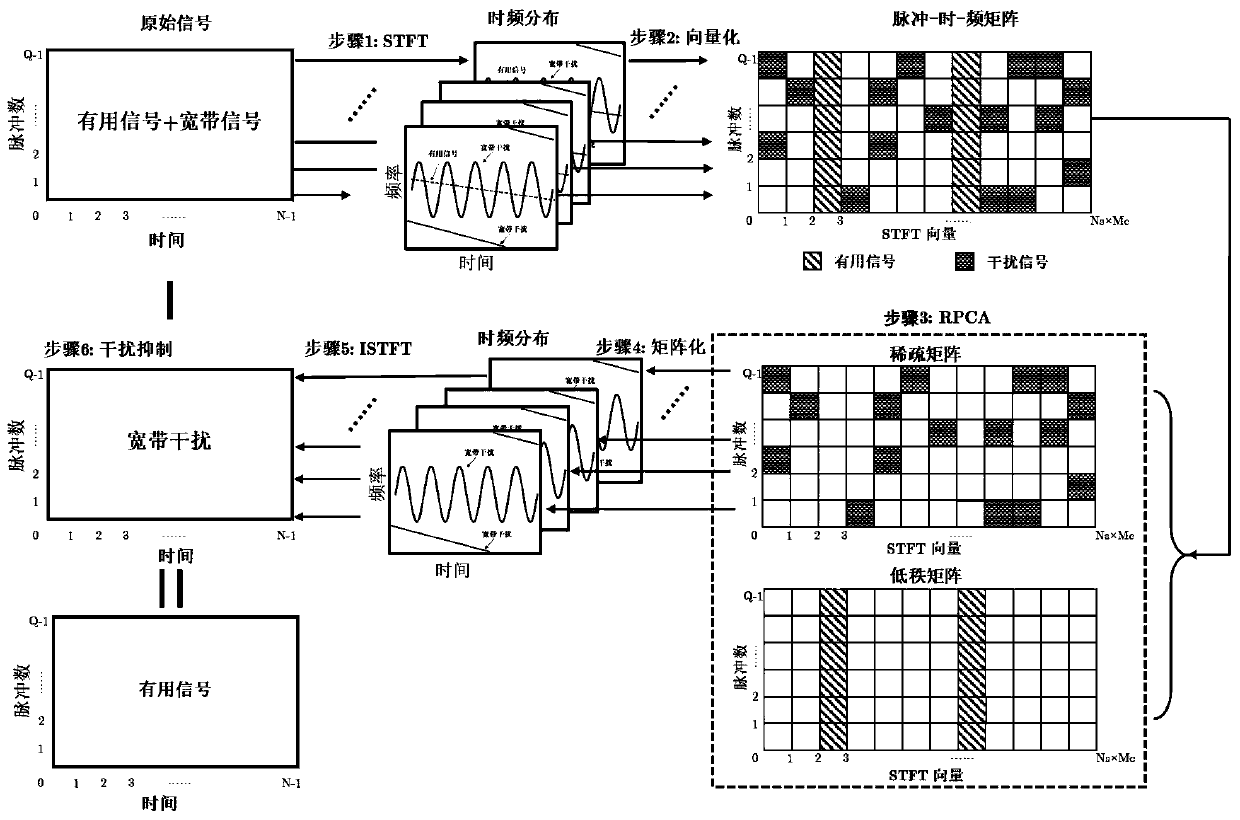
In order to overcome the existing problem of energy loss of useful signals based on short-time Fourier transform, the present invention transforms each pulse-echo data into the short-time Fourier transform domain. For useful signals, several adjacent pulses In the echo, the echo signal is constant or slowly changing, so it can be considered that the time-frequency distribution of the useful signal satisfies the low-rank characteristic in multiple pulses; and for the broadband interference signal, the interference signal transmits pulse repetition period In general, it will not be strictly consistent with the useful signal transmission cycle, which means that within the pulse repetition cycle of the useful signal, parameters such as the starting frequency, modulation frequency, modulation index, and initial phase will change relatively greatly. Within the pulse repetition period of , the interference signal does not have low-rank characteristics, as shown in 1

Method used


Image

  • Multi-dimensional domain joint SAR broadband interference suppression method based on low-rank matrix decomposition
  • Multi-dimensional domain joint SAR broadband interference suppression method based on low-rank matrix decomposition
  • Multi-dimensional domain joint SAR broadband interference suppression method based on low-rank matrix decomposition

Examples


Embodiment Construction

[0024] The present invention will be further described below in conjunction with the accompanying drawings and embodiments.

[0025] Step 1: Assuming that there are broadband interference signals in multiple pulses of the current echo data, the echo signal is expressed as X(n,q), where n represents the fast time sampling point, and q represents the number of pulses; the echo signal of Q pulses Perform the short-time Fourier transform respectively, expressed as:

[0026] STFT X,q =STFT I,q +STFT S,q +STFT N,q ,q=1,2,...,Q(1)

[0027] Among them, STFT X,q 、STFT I,q 、STFT S,q 、STFT N,q Expressed as the short-time Fourier transform matrix of the qth pulse echo signal, broadband interference signal, useful signal, and noise signal, the matrix STFT X,q 、STFT I,q 、STFT S,q 、STFT N,q The dimensions of are all N×M;

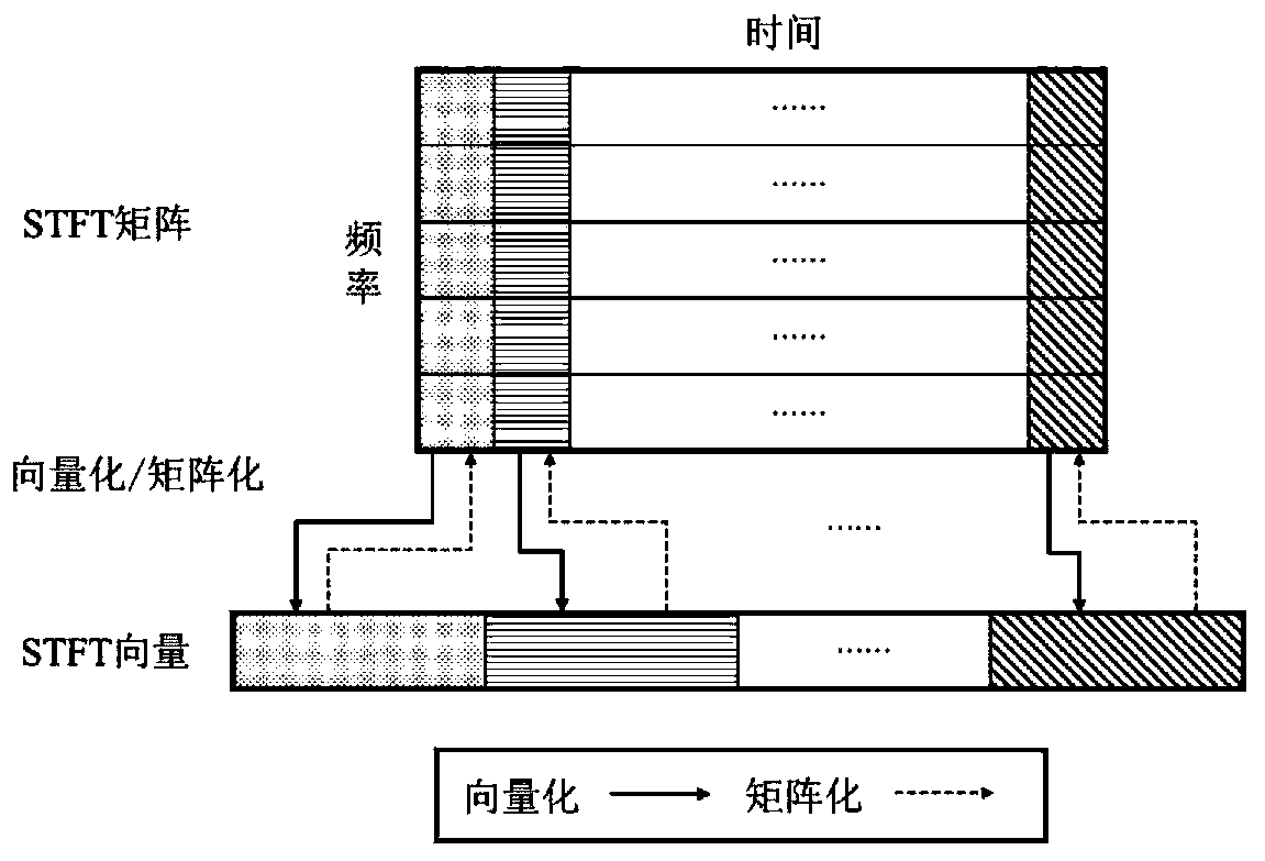
[0028] Step 2: Vectorize the short-time Fourier transform matrices of the Q pulse echo signals respectively, that is, pull the short-time Fourier transform ma...


PUM


Abstract

The invention provides a multi-dimensional domain joint SAR broadband interference suppression method based on low-rank matrix decomposition. Broadband interference signals exist in a plurality of pulses of current echo data. The short-time Fourier transform matrixes of the pulse echo signals are vectorized respectively; RPCA decomposition is performed to obtain a low-rank matrix and a sparse matrix; each row of the decomposed sparse matrix is rearranged into a short-time Fourier matrix form; the rearranged short-time Fourier matrix is subjected to inverse short-time Fourier transform, the reconstructed interference signal is subtracted from the original echo signal to realize broadband interference suppression, and data subjected to interference suppression is imaged by using an existingimaging algorithm to obtain a high-resolution image. According to the method, the problem of useful signal loss caused by time-frequency filtering is avoided, compared with a traditional method basedon energy characteristic difference, useful signal information can be effectively reserved while interference is suppressed, and the image quality after broadband interference suppression can be improved to a large extent.

Description

technical field [0001] The invention relates to the field of signals, in particular to a combined time-frequency-pulse multi-dimensional domain interference suppression method, which is suitable for broadband interference suppression with time-frequency aggregation characteristics in a time-frequency plane. Background technique [0002] Since Synthetic Aperture Radar (SAR) has the characteristics of all-day, all-weather work and wide-area surveillance, its application in battlefield reconnaissance and resource exploration has received more and more attention. In recent years, the rapid development of jamming technology poses a huge threat to SAR precise remote sensing technology. According to the bandwidth of the interference signal, the interference can be divided into narrow-band interference (Narrow-Band Interference, NBI) and wide-band interference (Wide-Band Interference, WBI). [0003] At present, narrowband interference suppression methods are relatively mature, such...

Claims


Application Information

Patent Timeline
IPC IPC(8): G01S7/292G01S13/90
CPCG01S7/2923G01S13/90
Inventor 粟嘉李浩江陶明亮崔国楠范一飞谢坚王伶张兆林韩闯宫延云
Owner NORTHWESTERN POLYTECHNICAL UNIV
Learn More