Reactive compensation control device and control method thereof

A control method and compensation control technology, applied in the direction of reactive power compensation, reactive power adjustment/elimination/compensation, etc., can solve the problem of increasing the maintenance cost of the reactive power compensation device, reducing the stability of the use of the reactive power compensation device, contactors and capacitors. It can shorten the maintenance cycle, prolong the service life, and improve the stability and reliability of use.

Inactive Publication Date: 2020-06-05
广东华利源电气设备有限公司
View PDF7 Cites 0 Cited by
  • Summary
  • Abstract
  • Description
  • Claims
  • Application Information

AI Technical Summary

Problems solved by technology

Among them, capacitor banks that have been used for a long time, as well as contactors and capacitor banks that are frequently switched are easily damaged, resulting in red...

Method used


Image

  • Reactive compensation control device and control method thereof
  • Reactive compensation control device and control method thereof
  • Reactive compensation control device and control method thereof

Examples


Embodiment Construction

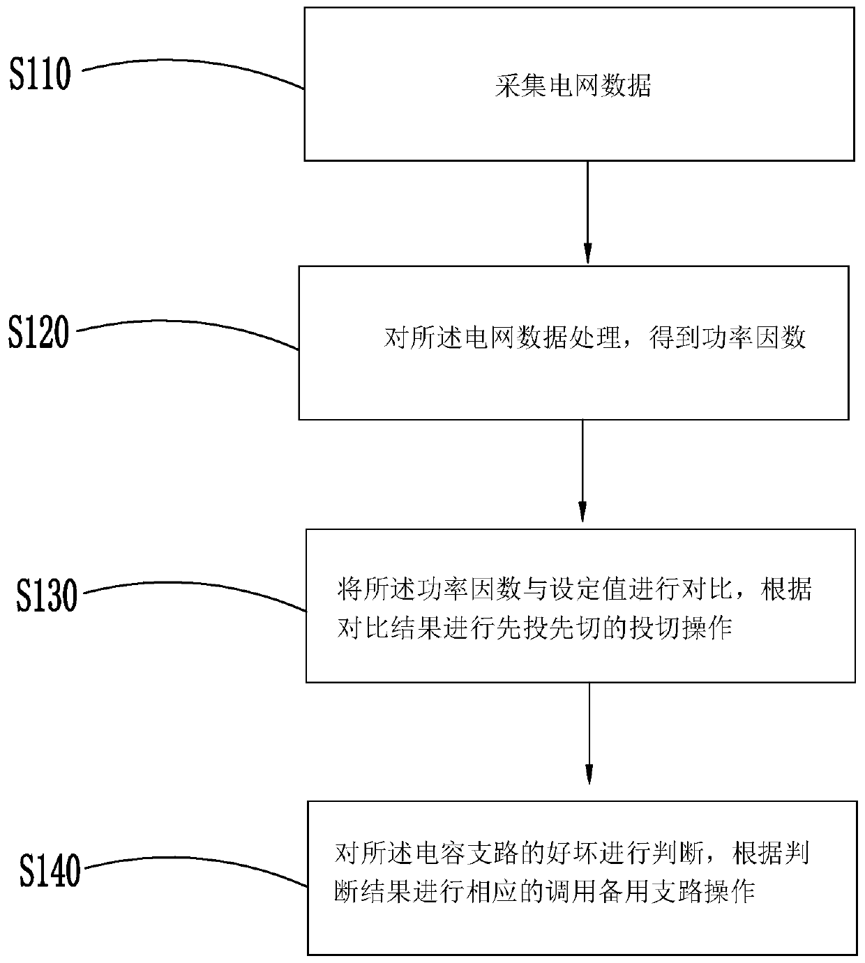
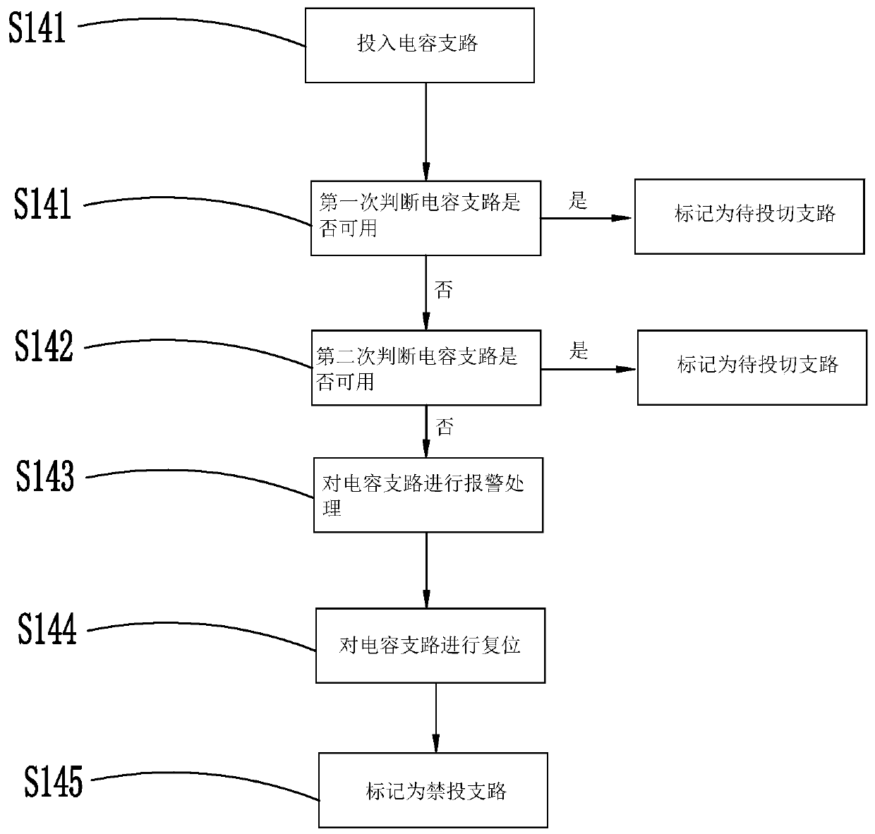
[0024] refer to figure 1 , the embodiment of the present invention provides a control method for reactive power compensation, including step S110, collecting grid data; step S120, processing the grid data to obtain a power factor; step S130, comparing the power factor with a set value, according to Comparing the results, perform the switching operation of switching first and switching first; step S140, judging whether the capacitor branch is good or bad, and correspondingly calling the backup branch operation according to the judgment result. By judging the quality of the capacitor branch and automatically calling the backup branch, not only the stability and reliability of the capacitor bank are improved, but also the service life of the compensation device is extended and the maintenance cycle of the reactive power compensation device is shortened.

[0025] In another embodiment, the set value includes input set value and cut-off set value. When the power factor is less than...


PUM


Abstract

The invention discloses a reactive compensation control method which is characterized by comprising the following steps: acquiring power grid data; processing the power grid data to obtain a power factor; comparing the power factor with a set value, and performing switching operation of switching first according to a comparison result; and judging whether the capacitor branch is good or not, and correspondingly calling the standby branch according to a judgment result. By judging the quality of the capacitor branch and automatically calling the standby branch, the use stability and reliabilityof the capacitor branch are improved, the service life of the compensation device is prolonged, and the maintenance period of the reactive power compensation device is shortened.

Description

technical field [0001] The invention relates to the field of electric power technology, in particular to a reactive power compensation control device and a control method thereof. Background technique [0002] In the daily power consumption environment, the running reactive power compensation device of the distribution network is mainly dynamic compensation. The switching mode makes a certain group of large-capacity capacitors or a certain group of small-capacity capacitors in the cabinet use for a long time, and other capacitor groups are used for a short time. Cut frequently. Among them, capacitor banks that have been used for a long time, and contactors and capacitor banks that are frequently switched are easily damaged, resulting in reduced stability of the reactive power compensation device and even short-term fault failure, which greatly increases the maintenance cost of the reactive power compensation device. Contents of the invention [0003] In order to solve the...

Claims


Application Information

Patent Timeline
IPC IPC(8): H02J3/18
CPCH02J3/18Y02E40/30
Inventor 黄伟坚吕振星黄茂强何卫强王靖梁远鹏黎伟健
Owner 广东华利源电气设备有限公司
Why Eureka
Try Eureka