Current control method of dual three-phase permanent magnet synchronous motor

A dual-three-phase permanent magnet and synchronous motor technology, which is applied in the direction of motor generator control, AC motor control, electronic commutation motor control, etc., can solve the problem of large winding current harmonic current component, large current harmonic total distortion rate, The problem of large difference in current given value can avoid the large total harmonic distortion rate of current, reduce the total harmonic distortion rate, and reduce the effect of influence

Active Publication Date: 2022-02-08
NAVAL UNIV OF ENG PLA
View PDF4 Cites 0 Cited by
  • Summary
  • Abstract
  • Description
  • Claims
  • Application Information

AI Technical Summary

Problems solved by technology

for figure 1 With two sets of winding average current feedback control strategies, the influence of the 6th harmonic current on the current loop can be completely eliminated; for figure 2 The control strategy of independent current feedback of the two sets of windings, the impact of the 6th harmonic current is relatively large, which will cause a relatively large current harmonic distortion (THD) in the two sets of windings, which will have an adverse effect on the long-term stable and reliable operation of the motor
[0007] To sum up, for a dual-three-phase permanent magnet synchronous motor with a certain imbalance in the two sets of windings, the average current feedback control strategy may cause the d-axis current and q-axis current of the two sets of windings to be equal to the current given value The difference is large, and the expected control effect cannot be achieved; the current control strategy of the independent current feedback of the two sets of windings may cause the 5th and 7th harmonic current components in the winding current to be relatively large, which is not conducive to the long-term stable and reliable operation of the motor

Method used


Image

  • Current control method of dual three-phase permanent magnet synchronous motor
  • Current control method of dual three-phase permanent magnet synchronous motor
  • Current control method of dual three-phase permanent magnet synchronous motor

Examples


Embodiment Construction

[0023] The present invention will be further described in detail below in conjunction with the accompanying drawings and specific embodiments to facilitate a clear understanding of the present invention, but they do not limit the present invention.

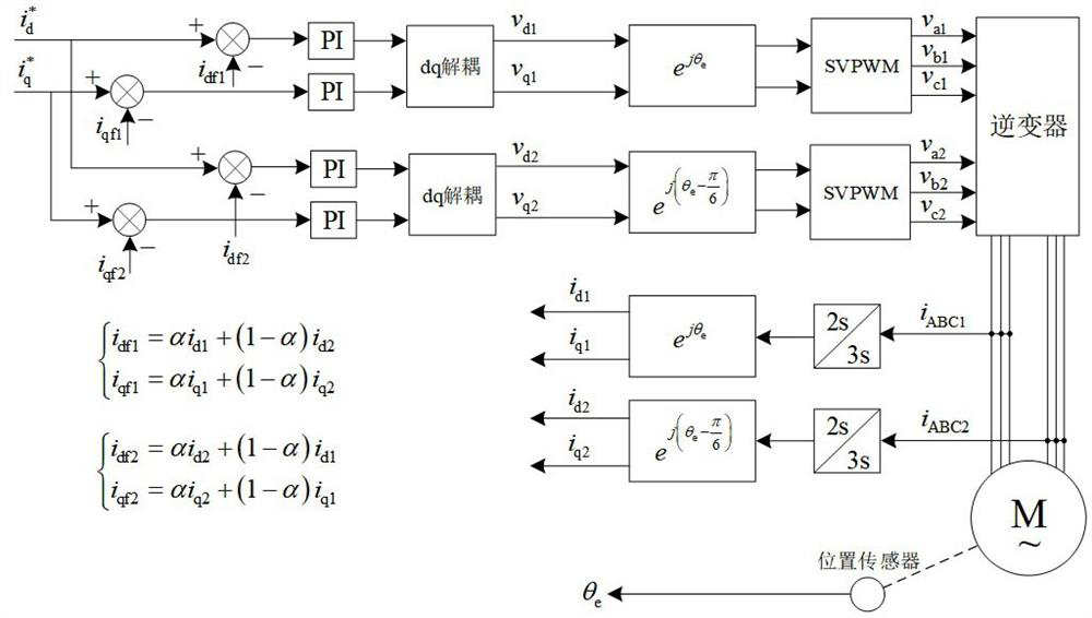
[0024] like image 3 As shown, in the current control strategy of the dual three-phase permanent magnet synchronous motor, two sets of rotor synchronous coordinate systems are set, and the second set of rotor synchronous coordinate systems lags behind the first set of rotor synchronous coordinate systems by 30 degrees in electrical angle. The vector control of the first set of windings is completed under the first set of rotor synchronous coordinate system, and the vector control of the second set of windings is completed under the second set of rotor synchronous coordinate system. The first set of windings has two current regulators, namely the d-axis current regulator and the q-axis current regulator, whose output is decoupled by ...


PUM


Abstract

The invention provides a current control method of a dual-three-phase permanent magnet synchronous motor, which is characterized in that: the rotor synchronous coordinate system is respectively set for the two sets of windings of the dual-three-phase permanent magnet synchronous motor; the difference between the two rotor synchronous coordinate systems is 30 degrees angle; both sets of windings include a d-axis current regulator and a q-axis current regulator; the feedback value of the d-axis current regulator of the first set of windings is a linear combination of the d-axis currents of the two sets of windings; the q-axis current of the first set of windings The feedback value of the regulator is the linear combination of the q-axis currents of the two sets of windings; the feedback value of the d-axis current regulator of the second set of windings is the linear combination of the d-axis currents of the two sets of windings; the feedback value of the q-axis current regulator of the second set of windings is the linear combination of the q-axis currents of the two sets of windings; setting the cross-coupling feedback coefficient is used to control the cross-coupling degree of the two sets of winding currents. The invention simultaneously overcomes the disadvantages of the independent current feedback control strategy and takes into account the advantages of the two current feedback control strategies.

Description

technical field [0001] The invention belongs to the control technology of permanent magnet synchronous motors, and in particular relates to a current control method of a double-three-phase permanent magnet synchronous motor. Background technique [0002] Compared with asynchronous traction motors, permanent magnet synchronous traction motors have the advantages of high power factor, high system efficiency, high torque density, small frequency converter capacity and strong dynamic response capability. Especially in the last two decades, rare earth permanent magnet materials have developed rapidly, and new permanent magnet materials have the characteristics of high remanence density, high magnetic energy product and high coercive force, which have led to the rapid development of permanent magnet synchronous motors. Most of the motors we use in our daily life are three-phase motors, and dual three-phase motors can achieve greater output torque with a smaller winding current, wh...

Claims


Application Information

Patent Timeline
Patent Type & Authority Patents(China)
IPC IPC(8): H02P21/22H02P25/22
CPCH02P21/22H02P25/22
Inventor 刘计龙肖飞麦志勤张伟伟高山连传强陈鹏朱志超李科峰
Owner NAVAL UNIV OF ENG PLA
Why Eureka
Try Eureka