

Foot tub with sterilization function
A footbath basin and functional technology, which is applied to the sanitary equipment for bathtubs, showers, toilets, etc., can solve the problems that cannot be removed, cleaned, and the winding rack cannot be removed and replaced separately, so as to avoid collisions.
- Summary
- Abstract
- Description
- Claims
- Application Information
AI Technical Summary
Problems solved by technology
Method used
Image

Examples
Embodiment 1
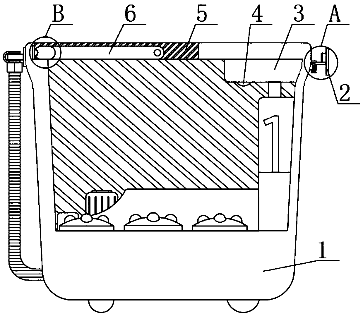
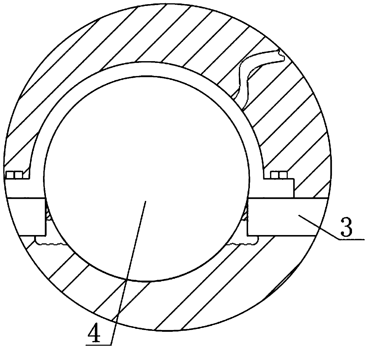
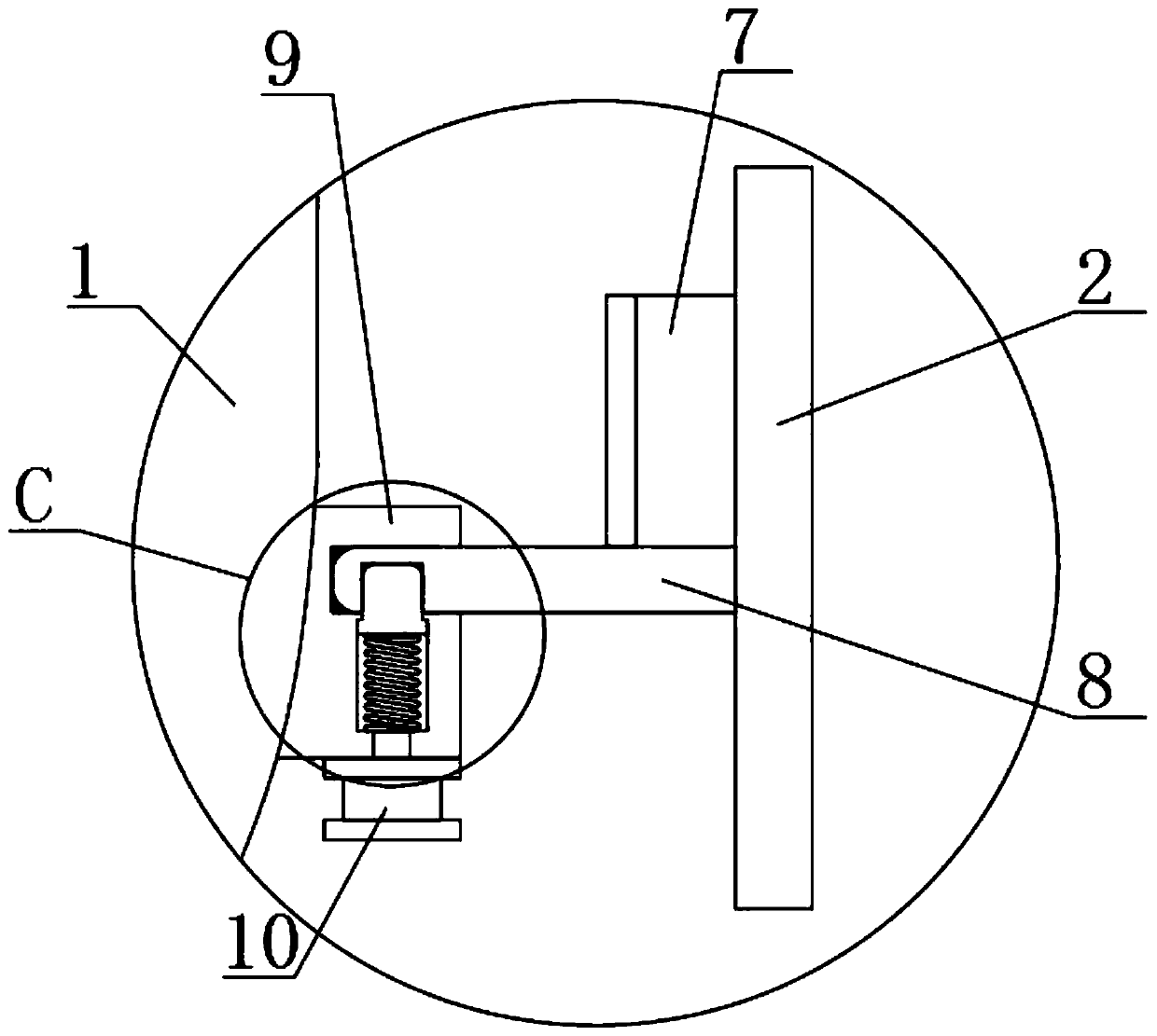
[0023] see Figure 1 to Figure 4 , the present invention provides a technical solution: a footbath with a sterilizing function, comprising a basin body 1 and an inner top seat 3 arranged on the inner top of the basin body 1, the top of the basin body 1 is provided with a basin opening 5, and the basin The inner side of the port 5 is rotatably connected with a handle 6, the outer side of the basin body 1 is provided with a winding frame assembly, the inner top seat 3 is fixed with a UV germicidal lamp 4, and the bottom surface of the inner top seat 3 is provided with a UV germicidal lamp. 4 Corresponding strip-shaped holes, the bottom of the UV germicidal lamp 4 penetrates through the strip-shaped hole to the bottom of the inner top seat 3, so that the UV germicidal lamp 4 can irradiate the inner side of the basin body 1 and the inner side of the basin body 1 when it is working. Sterilize with clean water, sealant is provided in the inner gap of the strip hole, the sealant here...
Embodiment 2
[0028] see Figure 1 to Figure 5 , the present invention provides a technical solution: a footbath with a sterilizing function, comprising a basin body 1 and an inner top seat 3 arranged on the inner top of the basin body 1, the top of the basin body 1 is provided with a basin opening 5, and the basin The inner side of the port 5 is rotatably connected with a handle 6, the outer side of the basin body 1 is provided with a winding frame assembly, the inner top seat 3 is fixed with a UV germicidal lamp 4, and the bottom surface of the inner top seat 3 is provided with a UV germicidal lamp. 4 Corresponding strip-shaped holes, the bottom of the UV germicidal lamp 4 penetrates through the strip-shaped hole to the bottom of the inner top seat 3, so that the UV germicidal lamp 4 can irradiate the inner side of the basin body 1 and the inner side of the basin body 1 by ultraviolet rays when it is working. Sterilize with clean water, sealant is provided in the internal gap of the strip...
PUM
 Abstract
Description
Claims
Application Information