


Quick Research
Generate reliable direction feasibility study reports for your R&D in just a few steps.

Technical Q&A
Discover and master advanced knowledge NOW. Basics, ideas, possibilities, all at once.

Find Solutions
As an expert in R&D theories, this can generate solutions to your technical problems instantly.

Evaluate Feasibility
Analyze your overall solution with one click, know your potential R&D risks in advance.

Monitor Landscape
Get weekly tech updates, stay abreast of the latest tech innovations and key insights.
Photocatalyst spraying device convenient to use
A technology of spraying device and photocatalyst, applied in the field of photocatalyst, can solve the problems of poor mixing effect of photocatalyst paint, affecting users' experience of using the spraying device, and easy coagulation or precipitation of photocatalyst paint, etc., so as to improve the use experience, good stirring function and structure. simple effect
- Summary
- Abstract
- Description
- Claims
- Application Information
AI Technical Summary
Problems solved by technology
Method used
Image

Examples
Embodiment 1
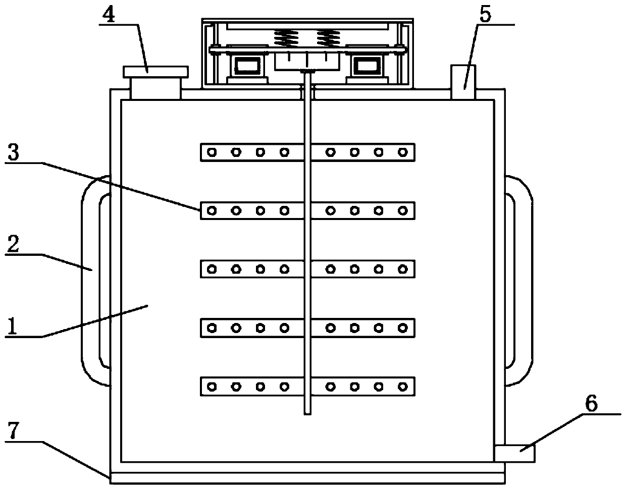
[0023] See Figure 1-Figure 3 , The present invention provides a technical solution: an easy-to-use photocatalyst spraying device, comprising a storage box 1, one end of the upper surface of the storage box 1 is provided with an integrated feed tube 4, the top of the feed tube 4 is provided with Sealing cover. The other end of the upper surface of the storage box 1 is provided with an integrated air inlet pipe 5. The storage box 1 and the air inlet pipe 5 are used in the prior art. One side of the storage box 1 is provided with a back strap 2 and a back strap 2 The material of is nylon, the use of the strap 2 is the prior art, the bottom end of the storage box 1 is provided with an integrally formed discharge tube 6, and the middle of the upper surface of the storage box 1 is provided with a stirring mechanism 3;
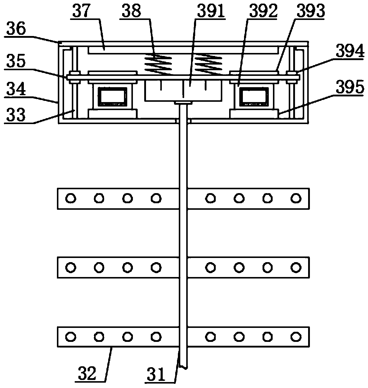
[0024] The stirring mechanism 3 includes a limit base 34, the top of the limit base 34 is provided with a protective cover plate 36, the lower surface of the protectiv...
Embodiment 2
[0033] On the basis of embodiment 1, in order to make the limiting effect of the limiting rod 33 better, in this embodiment, preferably, the limiting rod 33 has a cylindrical structure, and the bottom end of the limiting rod 33 is connected to the limiting base 34 It is fixedly connected by welding. In order to make the disassembly and assembly of the protective cover plate 36 more convenient, in this embodiment, preferably, the protective cover plate 36 and the limit base 34 are fixedly connected by bolts;
[0034] In order to make the limiting sleeve 394 have a better limiting effect on the limiting rod 33, in this embodiment, preferably, the limiting sleeve 394 has a hollow cylindrical structure, and the limiting sleeve 394 is provided through the support plate 35. The limit sleeve 394 and the support plate 35 are fixedly connected by welding;
[0035] In order to make the anti-skid effect of the storage box 1 better, in this embodiment, preferably, an anti-skid pad 7 is provide...
PUM
 Abstract
Description
Claims
Application Information
 - R&D Engineer
- R&D Manager
- IP Professional
- Industry Leading Data Capabilities
- Powerful AI technology
- Patent DNA Extraction
Browse by: Latest US Patents, China's latest patents, Technical Efficacy Thesaurus, Application Domain, Technology Topic, Popular Technical Reports.
© 2024 PatSnap. All rights reserved.Legal|Privacy policy|Modern Slavery Act Transparency Statement|Sitemap|About US| Contact US: help@patsnap.com