Direct current assistance based silicon steel cold rolling process
A technology of DC current and DC power supply, applied in metal rolling, manufacturing tools, metal rolling, etc., can solve the problems of increasing investment in fixed equipment, deteriorating the surface quality of finished products, adding additional equipment, etc., achieving small investment and improving surface processing Quality, reduce the effect of edge cracking and broken belt
- Summary
- Abstract
- Description
- Claims
- Application Information
AI Technical Summary
Problems solved by technology
Method used
Image
Examples
Embodiment 1
[0034] A cold rolling process of silicon steel based on DC current assistance. The silicon steel described in this embodiment is 1.5% non-oriented silicon steel, the thickness of the blank is 2 mm, and the thickness of the finished product is 0.5 mm.
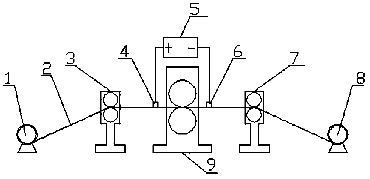
[0035] The silicon steel cold rolling process such as figure 1 Shown:
[0036] 1), first uncoil the silicon steel billet through the uncoiler 1, start the rolling mill 9, the rolled piece 2 passes through the front guide roller 3, the rolling mill 9 and the rear guide roller 7 to thread the strip, and the rolled piece 2 is coiled by the coiler 8 2 laps, the tension is established, the rolling mill 9 is accelerated, and the rolled piece 2 enters the stable rolling stage.
[0037] 2) When the rolling piece 2 enters the stable rolling stage, the lubricated rolling process is adopted, and the DC power supply 5 is turned on at the same time to apply a DC current to the rolling piece 2 for rolling.
[0038] 3) When entering the rol...
Embodiment 2
[0041] A cold rolling process of silicon steel based on DC current assistance. The silicon steel described in this embodiment is 2.5% non-oriented silicon steel, the thickness of the blank is 2 mm, and the thickness of the finished product is 0.35 mm.
[0042] The silicon steel cold rolling process such as figure 1 Shown:
[0043] 1), first uncoil the silicon steel billet through the uncoiler 1, start the rolling mill 9, the rolled piece 2 passes through the front guide roller 3, the rolling mill 9 and the rear guide roller 7 to thread the strip, and the rolled piece 2 is coiled by the coiler 8 3 laps, the tension is established, the rolling mill 9 accelerates, and the rolled piece 2 enters the stable rolling stage.
[0044] 2) When the rolling piece 2 enters the stable rolling stage, the lubricated rolling process is adopted, and the DC power supply 5 is turned on at the same time to apply a DC current to the rolling piece 2 for rolling.
[0045] 3) When entering the rolli...
Embodiment 3
[0048] A cold rolling process of silicon steel based on DC current assistance. The silicon steel described in this embodiment is 3.5% oriented silicon steel, the thickness of the blank is 2 mm, and the thickness of the finished product is 0.5 mm.
[0049] The silicon steel cold rolling process such as figure 1 Shown:
[0050] 1), first uncoil the silicon steel billet through the uncoiler 1, start the rolling mill 9, the rolled piece 2 passes through the front guide roller 3, the rolling mill 9 and the rear guide roller 7 to thread the strip, and the rolled piece 2 is coiled by the coiler 8 2.5 circles, the tension is established, the rolling mill 9 is accelerated, and the rolling piece 2 enters the stable rolling stage.
[0051] 2) When the rolling piece 2 enters the stable rolling stage, the lubricated rolling process is adopted, and the DC power supply 5 is turned on at the same time to apply a DC current to the rolling piece 2 for rolling.
[0052] 3) When entering the r...
PUM
| Property | Measurement | Unit |
|---|---|---|
| thickness | aaaaa | aaaaa |
| thickness | aaaaa | aaaaa |
| thickness | aaaaa | aaaaa |
Abstract
Description
Claims
Application Information
 - R&D
- Intellectual Property
- Life Sciences
- Materials
- Tech Scout
- Unparalleled Data Quality
- Higher Quality Content
- 60% Fewer Hallucinations
Browse by: Latest US Patents, China's latest patents, Technical Efficacy Thesaurus, Application Domain, Technology Topic, Popular Technical Reports.
© 2025 PatSnap. All rights reserved.Legal|Privacy policy|Modern Slavery Act Transparency Statement|Sitemap|About US| Contact US: help@patsnap.com

