Automatic bottle cap and top cap positioning and assembly line and operation method thereof

An assembly line and automatic positioning technology, applied in metal processing, metal processing equipment, manufacturing tools, etc., can solve problems such as low work efficiency and inapplicability, and achieve the effect of improving assembly efficiency and ensuring assembly quality.

Inactive Publication Date: 2020-06-09
CHINA THREE GORGES UNIV
View PDF6 Cites 14 Cited by
  • Summary
  • Abstract
  • Description
  • Claims
  • Application Information

AI Technical Summary

Problems solved by technology

[0002] For a type of bottle cap with a top cap, it is necessary to press-fit the top cap on the top of the cap. The traditional assembly method is mainly assembled manually. During the assembly process, the bottle cap is positioned on the On the bottom mold, then, position the top cover at the

Method used


Image

  • Automatic bottle cap and top cap positioning and assembly line and operation method thereof
  • Automatic bottle cap and top cap positioning and assembly line and operation method thereof
  • Automatic bottle cap and top cap positioning and assembly line and operation method thereof

Examples


Embodiment 1

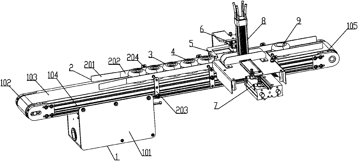
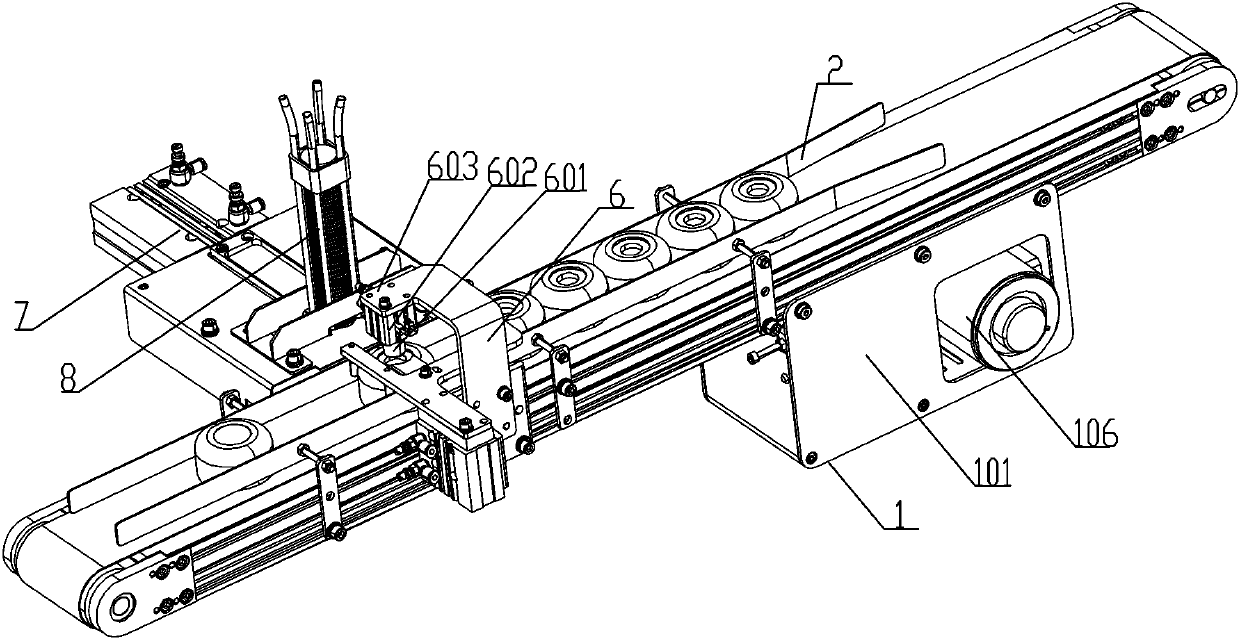
[0041] see Figure 1-4 , bottle cap top cap automatic positioning assembly line, which includes a conveyor 1 for conveying bottle caps, the feed end of the conveyor 1 is provided with a feed guide structure 2, and the end of the feed guide structure 2 is provided with a useful For the positioning mechanism 5 for positioning the wine cap, one side of the location of the positioning mechanism 5 is equipped with a pushing device 7 for pushing the loading of the top cover, and the pushing device 7 is used for storing the top cover. The storage mechanism 8 cooperates to realize the automatic upper cover, and the other side of the position of the positioning mechanism 5 is equipped with a press-fitting mechanism 6 for press-fitting the top cover. This assembly line can be used for automatic press-fitting and assembly of the cover plate on the top of the bottle cap, and can automatically position and press-fit it, thereby greatly improving its assembly efficiency and ensuring the ass...

Embodiment 2

[0051] The operation method of the automatic positioning assembly line for the top cap of the bottle cap comprises the following steps:

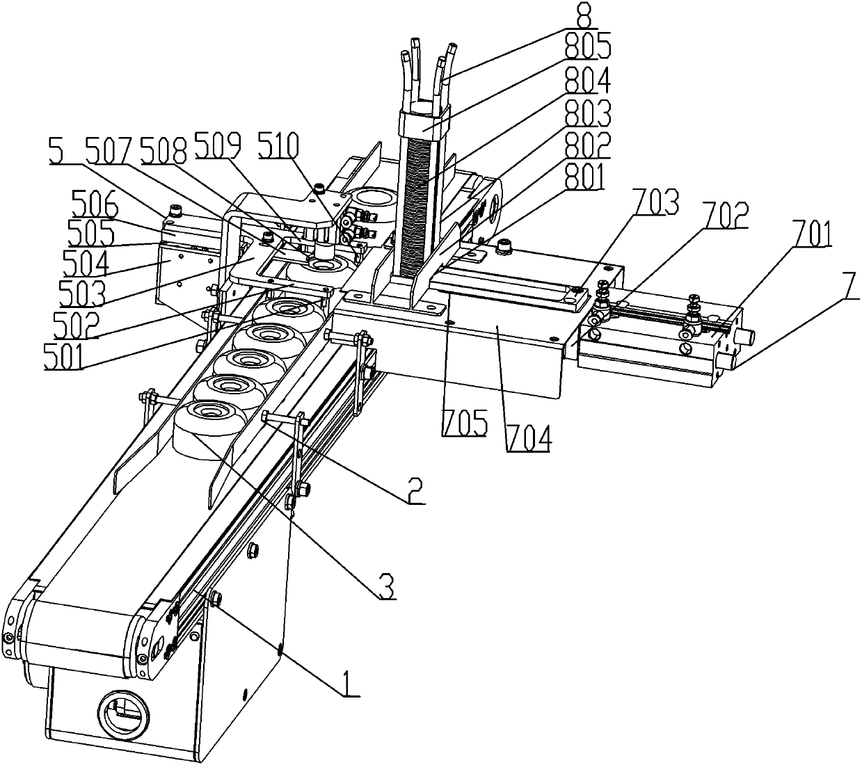
[0052] Step 1: Store the top cover 804 to be assembled between the columns 803 of the storage mechanism 8;

[0053] Step 2: Start the conveyor 1, convey the bottle cap 3 through the conveyor 1, and the bottle cap 3 enters the positioning mechanism 5 through the feeding guide structure 2;

[0054] Step 3: Start the positioning mechanism 5, drive the positioning lifting plate 503 to lift through the positioning lifting cylinder 505, and then drive the corresponding head stopper column 501 and tail stopper column 510 to realize lifting, and then limit the position of the bottle cap 3 to make it positioned on the conveyor belt 103;

[0055] Step 4: After the bottle cap 3 is positioned, start the pushing device 7, push the top cover push plate 703 through the push material cylinder 701, and then push the top cover 804 stored in the storage mecha...


PUM


Abstract

The invention provides an automatic bottle cap and top cap positioning and assembly line and an operation method thereof. The automatic bottle cap and top cap positioning and assembly line comprises aconveyor for conveying a bottle cap; the feeding end of the conveyor is provided with a feeding guide structure; the tail end of the feeding guide structure is provided with a positioning mechanism for positioning the wine cap; a pushing device for pushing a top cap to be fed is installed on one side face of the portion where the positioning mechanism is located; the pushing device is matched with a storage mechanism used for storing the top cap to achieve automatic cap feeding; and a pressing mechanism used for pressing the top cap is arranged on the other side face of the portion where thepositioning mechanism is located. The automatic bottle cap and top cap positioning and assembly line can be used for automatically pressing and assembling a cover plate at the top of the bottle cap and automatically positioning and pressing the cover plate, so that the assembly efficiency is greatly improved, and the assembly quality is guaranteed.

Description

technical field [0001] The invention belongs to the field of bottle cap automatic assembly equipment, and in particular relates to a bottle cap top cap automatic positioning assembly line and an operation method. Background technique [0002] For a type of bottle cap with a top cap, it is necessary to press-fit the top cap on the top of the cap. The traditional assembly method is mainly assembled manually. During the assembly process, the bottle cap is positioned on the On the bottom mold, then, position the top cover at the position to be assembled of the bottle cap, start the press-fitting cylinder to press down the top cover, and then complete the assembly of a bottle cap. The above-mentioned manual assembly method has relatively low work efficiency, and The labor intensity of the operators cannot be applied to [0003] High volume assembly needs. Contents of the invention [0004] In order to solve the above technical problems, the present invention provides an autom...

Claims


Application Information

Patent Timeline
IPC IPC(8): B23P19/027B23P19/00
CPCB23P19/001B23P19/027
Inventor 邓少华袁伟邹巧玲董元鑫
Owner CHINA THREE GORGES UNIV
Why Eureka
Try Eureka