Automatic centering and locking device of numerical control slotting machine

A technology of automatic centering and locking device, applied in the direction of positioning device, clamping, supporting, etc., can solve the problem of incapable locking device and high-precision automatic centering device fusion, achieve simple and convenient switching, eliminate errors , the effect of high-precision centering ability

Active Publication Date: 2020-06-09
SHANGHAI MARITIME UNIVERSITY
View PDF5 Cites 1 Cited by
  • Summary
  • Abstract
  • Description
  • Claims
  • Application Information

AI Technical Summary

Problems solved by technology

[0003] In view of the above-mentioned problems, the purpose of the present invention is to provide an automatic centering locking device for a numerical control slotting machine, which solves the problem that the locking device and a high-precision automatic centering device cannot be integrated together, and provides a locking device that can be locked at will. Tightening and loosening with high-precision self-centering CNC slotting fixture

Method used


Image

  • Automatic centering and locking device of numerical control slotting machine
  • Automatic centering and locking device of numerical control slotting machine
  • Automatic centering and locking device of numerical control slotting machine

Examples


no. 1 example

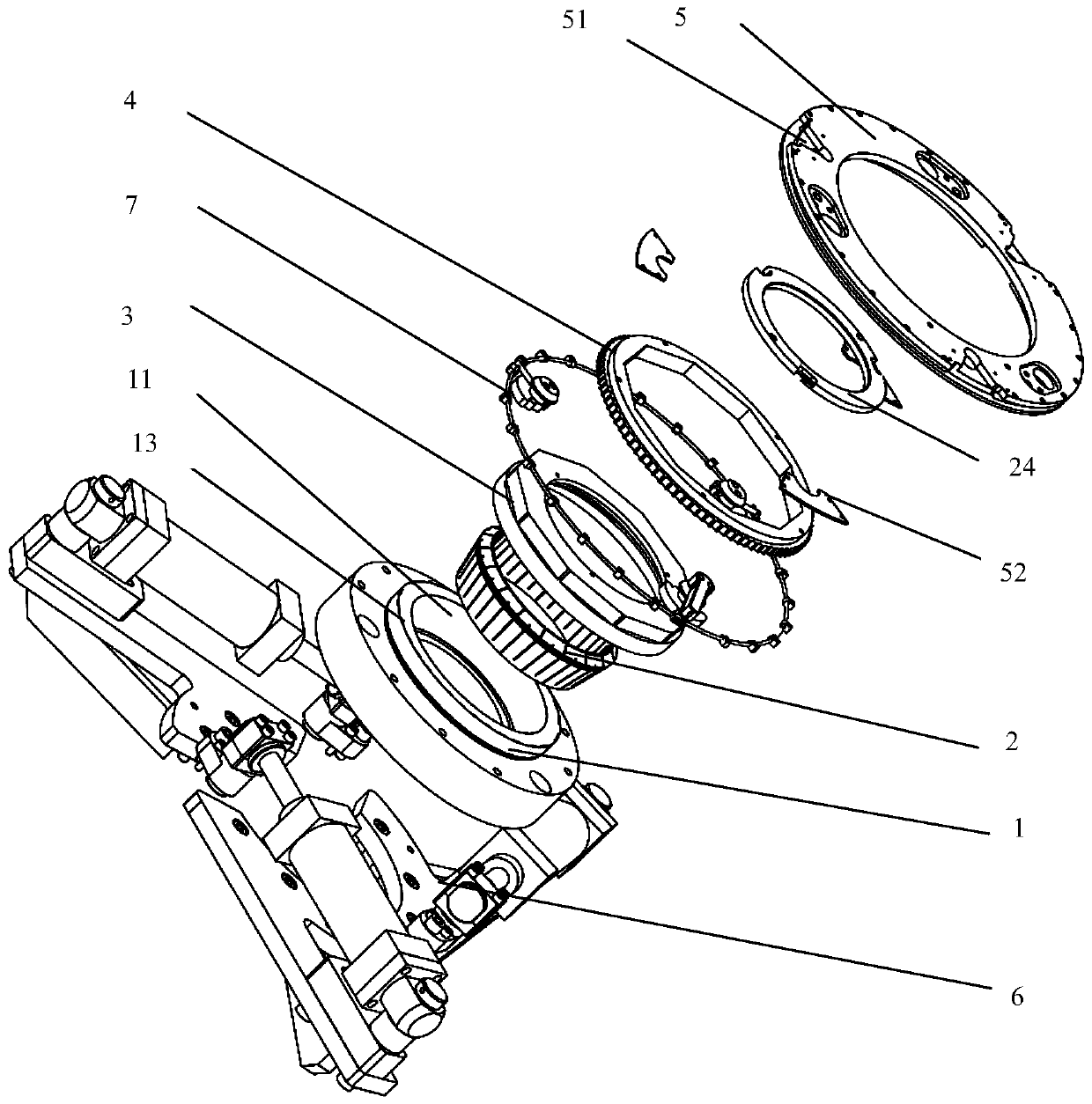
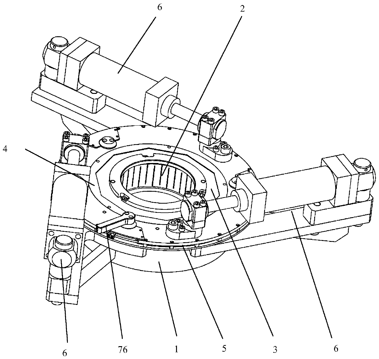
[0043] Such as figure 1 , figure 2 , image 3 with Image 6 As shown, the first preferred automatic centering locking device for CNC slotting machine is shown, including: a locking base 1, an elastic clamp 2 is arranged inside the locking base 1, and the elastic clamp 2 is tightened and clamped after moving downward. Holding the workpiece, there is a certain space in the vertical direction between the elastic clamp 2 and the locking base 1, which can be used for the elastic clamp 2 to move up and down. When the elastic clamp 2 is forced to move downward, the locking base 1 compresses the elastic clamp 2, and the elastic clamp 2 can clamp the workpiece after shrinking, and after the elastic clamp 2 puts down the workpiece, it moves upwards by its own elastic force to realize reset.

[0044] In addition, as a preferred embodiment, such as image 3 , Image 6 with Figure 11 As shown, the automatic centering locking device of the CNC slotting machine also includes: a lock ...

no. 2 example

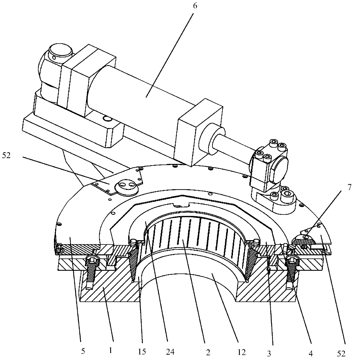
[0057] Please continue to see figure 1 , figure 1 with Image 6 As shown, the second preferred automatic centering locking device for CNC slotting machine is shown, including: a locking base 1, the radial section of the locking base 1 is circular, and the inside of the locking base 1 is arranged along the horizontal direction Annular step 15, the inner diameter of the locking base 1 gradually increases from the annular step 15 to its upper port, the inner diameter of the locking base 1 below the annular step 15 is the same, and the inside of the locking base 1 is provided with elastic clamps 2, elastic clamps 2 Located on the upper side of the annular step 15, the elastic clamp 2 has a relative bottom end 21 and a top end 22, and the radial section of the elastic clamp 2 is circular; along the axial direction of the elastic clamp 2, the outer diameter of the elastic clamp 2 is defined by the top end 22 gradually decreases toward the bottom end 21, the outer wall of the elast...


PUM


Abstract

The invention discloses an automatic centering and locking device of a numerical control slotting machine. The automatic centering and locking device of the numerical control slotting machine comprises a locking base, a locking nut, a lock inner ring, a lock outer ring, a cylinder power device and a reversing device, wherein an elastic clamp is arranged in the locking base, and the elastic clamp tightens and clamps a workpiece after moving downwards; the locking nut is in threaded connection with the locking base, and is provided with an inclined surface I for contacting with the upper end surface of the elastic clamp; the lock inner ring and the lock outer ring are concentrically arranged on the locking nut, and the lock outer ring is arranged on the outer side of the lock inner ring; thecylinder power device is installed on the locking base; and the reversing device is arranged in the lock outer ring, and the reversing device and the lock inner ring form a bidirectional ratchet structure. The cylinder power device pushes the lock outer ring to rotate so as to drive the lock inner ring and the locking nut to rotate, the elastic clamp is compressed and loosened by the locking nutso as to clamp and loosen the workpiece, the elastic clamp and the workpiece are concentrically installed, and automatic centering of the workpiece in the clamping process is guaranteed.

Description

technical field [0001] The invention relates to the technical field of clamp devices, in particular to an automatic centering locking device. Background technique [0002] At present, most of the workpieces in my country, especially large workpieces, are clamped on the slotting machine. Most of the slotting machines are clamped and fixed by three-grip chucks, special tooling, self-made tooling or assembly fixtures. Due to the variety of workpieces Many, the workpiece is from one station to another, one process to another process, or one machine tool to another machine tool. During the clamping and switching process of the workpiece, various fixtures need to spend a lot of time due to the complicated clamping method of the workpiece. A lot of time is spent on installation and alignment, which increases the unnecessary downtime of the machine tool and reduces the machining accuracy; secondly, there are human errors in the clamping and alignment, and the replacement of different ...

Claims


Application Information

Patent Timeline
Patent Type & Authority Applications(China)
IPC IPC(8): B23Q3/08
CPCB23Q3/08
Inventor 何鹏飞刘龙
Owner SHANGHAI MARITIME UNIVERSITY
Why Eureka
Try Eureka