Dual-motor transmission structure and wall cutting machine provided with the same

A transmission structure and dual-motor technology, which is applied in the direction of electric components, electrical components, electromechanical devices, etc., can solve the problems of unreasonable setting of the dual-motor transmission structure, machine fragility, and small torque, so as to avoid machine failure and easy heat dissipation , the effect of increasing the torque

Pending Publication Date: 2020-06-09
上海得宴电动工具有限公司
View PDF0 Cites 0 Cited by
  • Summary
  • Abstract
  • Description
  • Claims
  • Application Information

AI Technical Summary

Problems solved by technology

[0007] The present invention aims to overcome the technical problems of unreasonable setting of the dual-motor transmission structure, small torque, fragile machine, and large volume in the above-mentioned prior art.

Method used


Image

  • Dual-motor transmission structure and wall cutting machine provided with the same
  • Dual-motor transmission structure and wall cutting machine provided with the same
  • Dual-motor transmission structure and wall cutting machine provided with the same

Examples


Embodiment 1

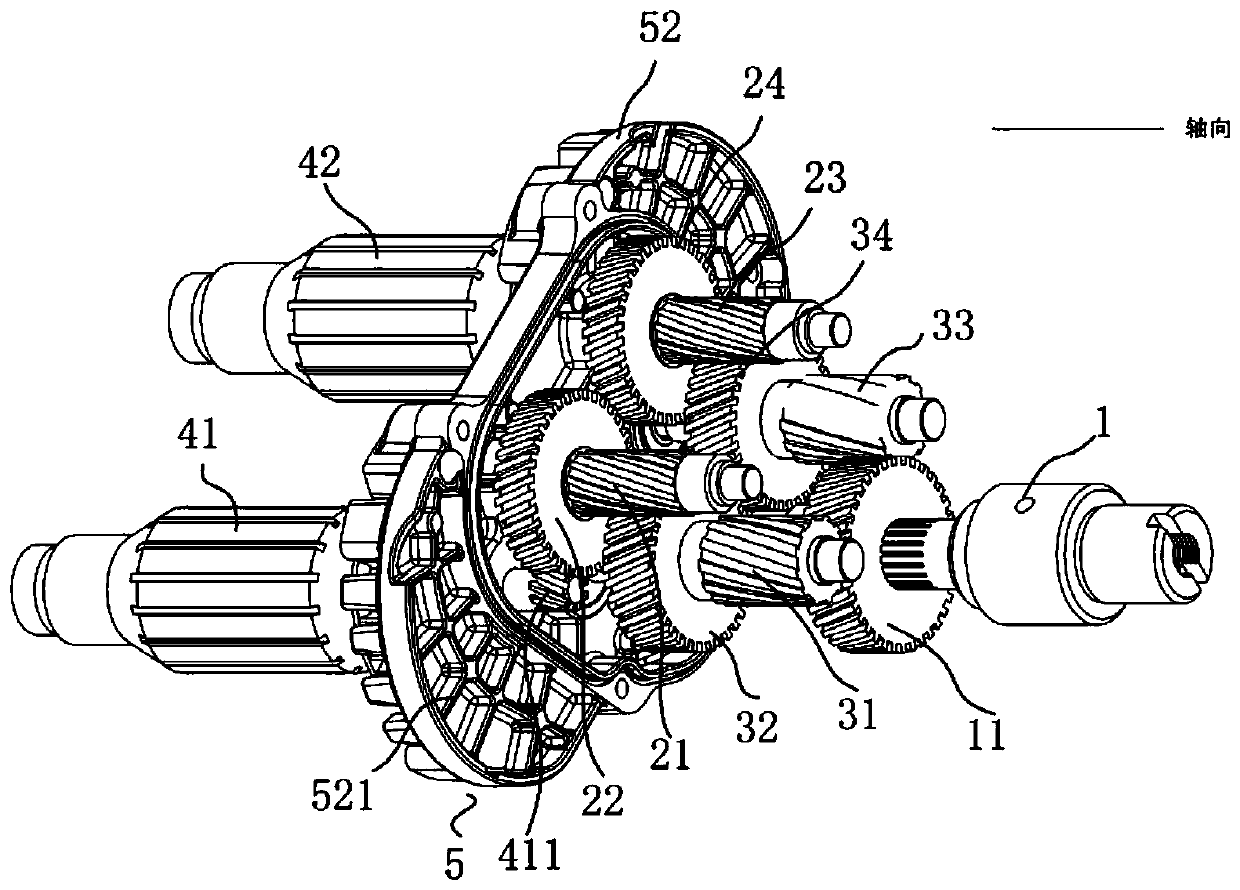
[0042] Such as figure 1 and figure 2 As shown, a transmission structure of a double motor, the double motor includes a first motor (not shown in the figure) and a second motor (not shown in the figure), and the rotor (41, 42) is arranged in the motor, and the rotor Including the first rotor 41 in the first motor and the second rotor 42 in the second motor, the transmission structure is connected to the two motors, and the transmission structure includes the main shaft 1, the main shaft gear 11 and the transmission wheel set connected in sequence , the transmission wheel set includes at least two delivery wheel sets (21, 22, 23, 24 or 31, 32, 33, 34), and the transmission connection between adjacent delivery wheel sets, the delivery wheel set (21, 22 , 23,24 or 31,32,33,34) comprise the first gear shaft (21,31), the second gear shaft (23,33), the first plate gear connected with the first gear shaft (21,31) (22,32), the second plate gear (24,34) connected with the second gear...

Embodiment 2

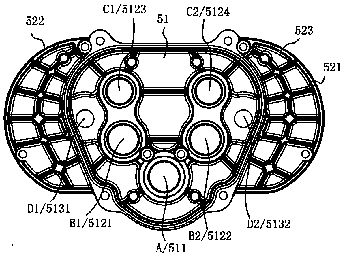
[0048] Such as figure 1 and figure 2 As shown, on the basis of Embodiment 1, there is also the following technical solution. On the same plane perpendicular to the axis of the main shaft 1, with the axis A of the main shaft 1 as the apex, the axis of the first stage gear shaft 21 C1, the axis A of the main shaft 1, and the axis C2 of the second-stage gear shaft 23 form an angle α1;

[0049] Taking the axis A of the main shaft 1 as the apex, the axis B1 of the first-stage gear shaft 31, the axis A of the main shaft 1, and the axis B2 of the second-stage gear shaft 33 form an included angle α2;

[0050] With the axis A of the main shaft 1 as the vertex, the angle α3 is formed between the axis D1 of the first rotor 41, the axis A of the main shaft 1, and the axis D2 of the second rotor 42; the degrees of α1 and α2 The relationship is, α1<α2<180 degrees, α3<180 degrees. In this embodiment, α1 is 120 degrees, α2 is 170 degrees, and α3 is 168 degrees.

Embodiment 3

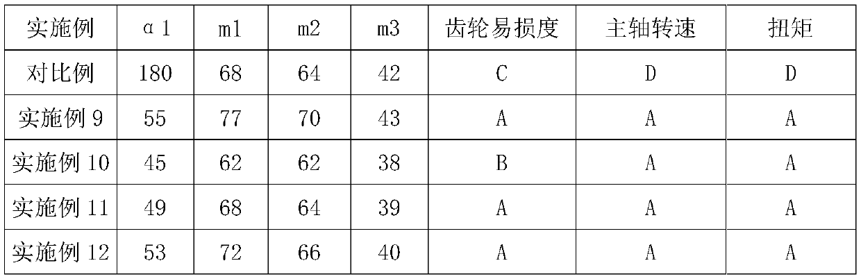
[0052] Such as figure 1 and figure 2 As shown, on the basis of Examples 1 and 2, there is also the following technical solution, the included angle α1, the included angle α2, 75 degrees ≤ α2 ≤ 115 degrees, 45 degrees ≤ α1 ≤ 65 degrees. 105°≤α3≤109°, the degree of α3 can be 105°, 106°, 107°, 108°, 109°. The degrees of α1 and α2 can be adjusted within the interval of 30 degrees ≤ α2-α1 ≤ 50 degrees, and the difference between α2-α1 can be 30 degrees, 32 degrees, 35 degrees, 40 degrees, 45 degrees, 50 degrees.


PUM


Abstract

The invention relates to a dual-motor transmission structure which comprises a spindle, a spindle gear and a driving wheel set sequentially connected, wherein the driving wheel set comprises at leasttwo conveying wheel sets; every two adjacent conveying wheel sets are in drive joint; each of the conveying wheel sets comprises a first gear shaft, a second gear shaft, a first plate gear connected with the first gear shaft, and a second plate gear connected with the second gear shaft; the first gear shaft and the second gear shaft are symmetrically arranged on the two sides of the spindle; and afirst secondary gear shaft and a second secondary gear shaft are arranged between the spindle and the plane of a first primary gear shaft and a second primary gear shaft. The invention further relates to a wall cutting machine provided with the dual-motor transmission structure. The dual-motor transmission structure can increase the torque and the output speed, reduces the size and prolongs the service life.

Description

technical field [0001] The invention relates to a transmission structure of double motors and a wall cutting machine with the transmission structure. Background technique [0002] The wall cutting machine is a machine for cutting concrete walls, but the pressure of the existing wall cutting machine is on one side of the gear for a long time, which leads to serious mechanical wear of the gear bearings, and also causes the machine to Stuck and smoldering, low efficiency, small output torque, slow cutting speed, short service life and high labor cost. The power of a motor is usually small (3.5KW), the output torque is small (80KN ~ 85KN), and the cutting speed is slow (2M ~ 2.5M / h). If the power of the motor is increased, a huge cost is required, and the improvement of torque and cutting speed is also limited. [0003] If two motors are installed to increase the power, on the one hand, the power of the two motors needs to be synchronized. In addition, since the two motors are...

Claims


Application Information

Patent Timeline
Patent Type & Authority Applications(China)
IPC IPC(8): B28D1/22B28D7/00H02K7/116H02K7/20
CPCB28D1/22B28D7/005H02K7/116H02K7/20
Inventor 李学亚朱加增
Owner 上海得宴电动工具有限公司
Why Eureka
Try Eureka