Clothing hanging conveying system

A transmission system and hanging technology, which is applied to sewing tools, conveyors, transportation and packaging, etc. It can solve the problems of affecting the efficiency of garment making, the bumping of the hanger wheel, and the mismatch between the hanger wheel and the connecting track. To achieve the effect of improving clothing efficiency and maintaining stability

Pending Publication Date: 2020-06-09
佛山市顺德区宏盈制衣有限公司
View PDF0 Cites 11 Cited by
  • Summary
  • Abstract
  • Description
  • Claims
  • Application Information

AI Technical Summary

Problems solved by technology

However, in the process of the hanger wheel being transported on the track, or turning into the station, or returning to the track from the workstation, it often happens that the hanger wheel does not match the connecting track, causing the hanger wheel to bump or the hanger wheel to fall completely. The situation of falling, resulting in the hanger wheels can not be better transported on the track, which affects the efficiency of the entire garment making, but also increases the unnecessary workload of the staff

Method used


Image

  • Clothing hanging conveying system
  • Clothing hanging conveying system
  • Clothing hanging conveying system

Examples


Embodiment 1

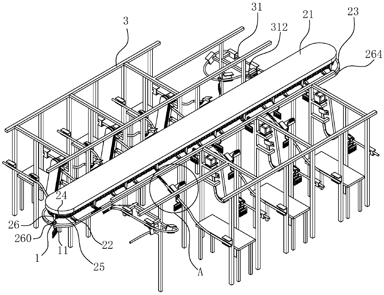
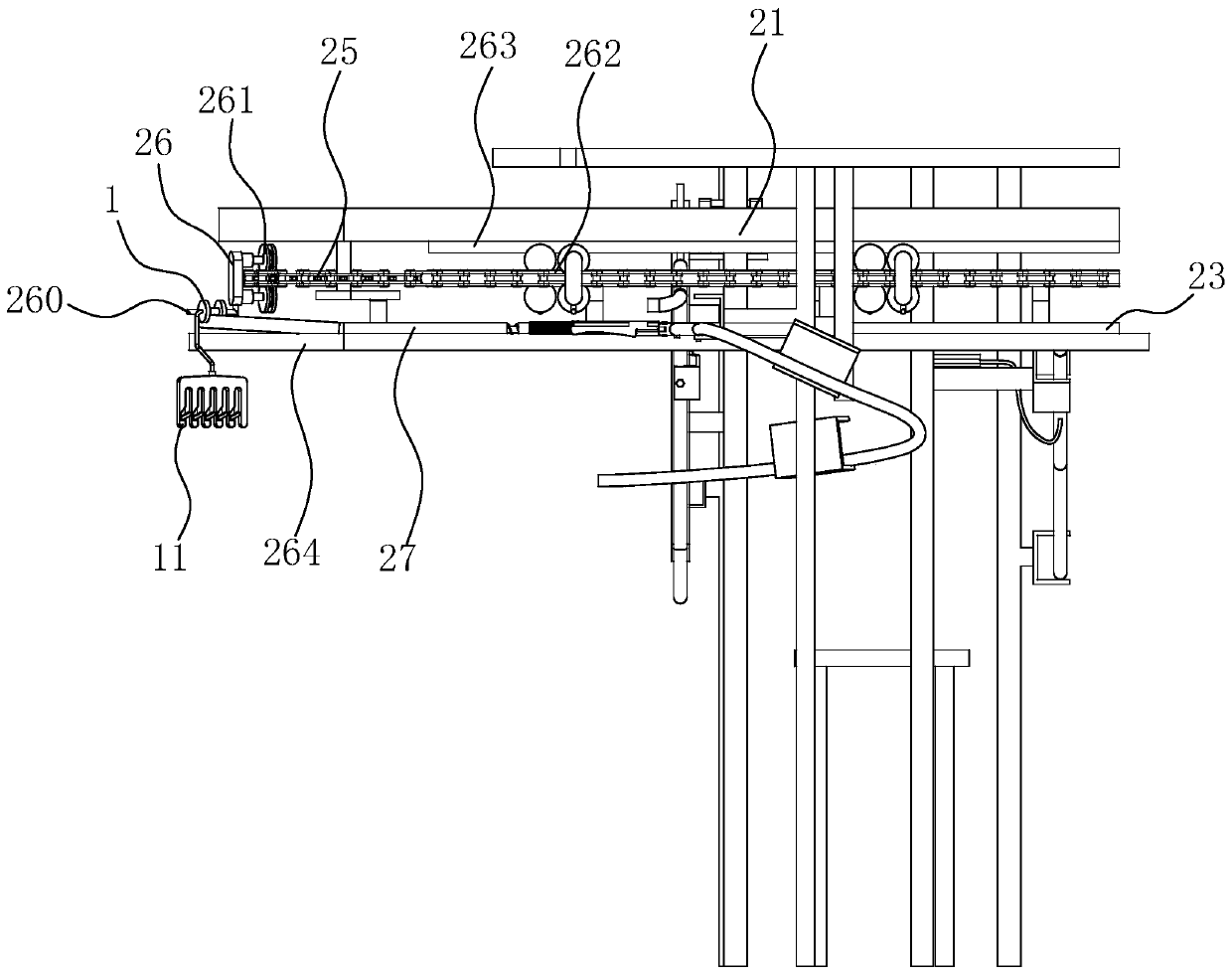
[0040] A garment hanging transmission system, such as figure 1 , image 3 As shown, the transmission assembly is suspended and fixed at the top position of the working environment, and the transmission assembly can be transported by the hanger wheel 1. In this embodiment, the transmission assembly includes a fixed frame 21, and the top position of the fixed frame 21 is suspended At the top position of the working environment, a plurality of "L"-shaped installation bars 22 are vertically arranged at the bottom position of the fixed frame 21, and at the same time, a plurality of sprockets are rotatably connected at the inner bottom position of the fixed frame 21 24. The sprockets 24 are installed uniformly and horizontally along the extension direction of the fixed frame 21 at the bottom position of the fixed frame 21, and an integrally closed transmission chain 25 is wound and connected at the wheel wall positions of these sprockets 24. The sprocket 24 is driven by a power par...

Embodiment 2

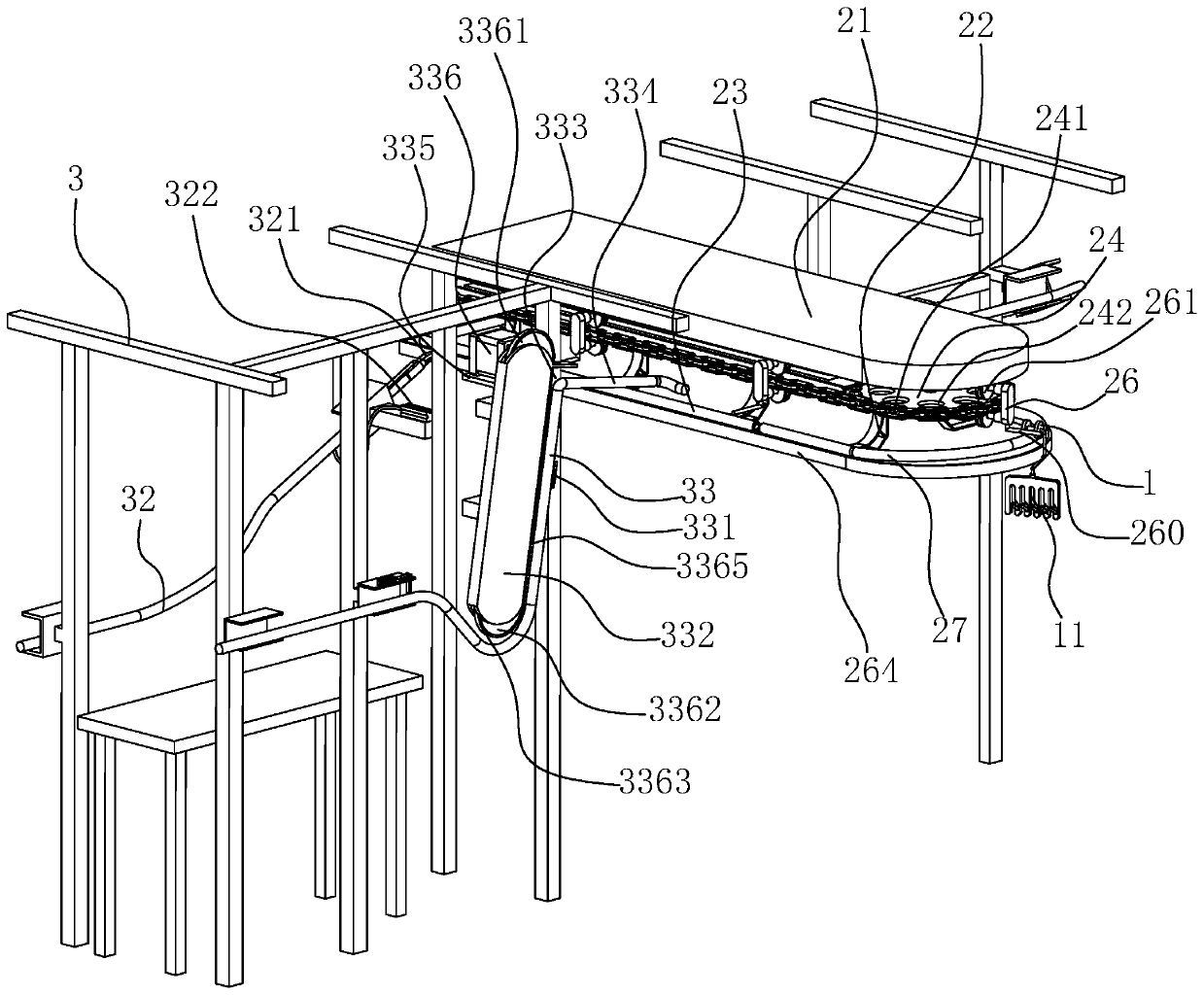
[0053] In this embodiment, the difference between this embodiment and Embodiment 1 lies in the difference of the station output components, such as figure 1 , Figure 7 As shown, the station output assembly includes a second inbound rail 32 , which is installed on the support 3 and just located at one side of the main transport rail 23 .

[0054] An abutment head 321 is arranged at the end position of the second inbound track 32 close to the main transmission rail 23, and at the same time, on the abutment head 321, a second auxiliary that can change the track of the clothes hanger wheel 1 to the second inbound track 32 is installed. Connecting piece, in this embodiment, the second auxiliary connecting piece includes a card slot 323 opened at the side wall of the main transmission rail 23 and consistent with the extension direction of the main transmission rail 23, and the abutting joint 321 is close to the card slot 323 A hook 324 is fixed at one end, and the hook 324 is matc...


PUM


Abstract

The invention relates to a clothing hanging conveying system, and belongs to the technical field of clothing product conveying equipment. The clothing hanging conveying system comprises a conveying assembly suspended and fixed to the top of a working environment, steering assemblies are arranged at the two ends of the conveying assembly, and an auxiliary conveying assembly is arranged at a rail ofthe conveying assembly; the conveying assembly comprises a fixed frame suspended and fixed to the top of the working environment, mounting strips fixed to the bottom of the fixed frame and overall inan L shape, main conveying rails parallelly arranged on the multiple mounting strips in a two-phase symmetry mode and located at the bottom of the fixed frame, and a driving piece mounted on the inner wall of the fixed frame; and a support is vertically fixed to the side walls of the main conveying rails, the position, close to the main conveying rails, of the support is provided with a station output assembly and a station input assembly, hanger wheels are slidably connected to top face rails of the main conveying rails, and the sides, away from the main conveying rails, of the hanger wheelsare provided with hangers.

Description

technical field [0001] The invention relates to the technical field of clothing product transmission equipment, in particular to a clothing hanging transmission system. Background technique [0002] Garment production is a labor-intensive industry. Garment production requires a lot of workers for each position from raw material fabrics to cutting, proofing, sewing, and ironing. Especially in the sewing department, each sewing machine or other equipment has a worker to complete a process, such as front body, back body, sleeves, etc. How to solve labor shortage, improve production efficiency and product quality is a problem faced by every garment manufacturer. [0003] With the development of industrial automation, automation equipment has been widely used, especially the production line of the garment suspension system. The production data should be timely and accurate, the management should be refined, the production efficiency is high, the operation is convenient, and the ...

Claims


Application Information

Patent Timeline
IPC IPC(8): B65G17/20B65G21/22A41H43/02
CPCA41H43/0242B65G17/20B65G21/22B65G2201/0229
Inventor 毛贤芬巨龙欧阳美珍张可鸣
Owner 佛山市顺德区宏盈制衣有限公司
Why Eureka
Try Eureka