
Bearing structure member used for wind power blade and preparation method thereof

A load-bearing structure, wind power blade technology, applied in the direction of wind power generation, wind motor combination, mechanical equipment, etc., can solve the problems of reducing structural rigidity and strength, so as to improve the overall bearing capacity, improve the efficiency and effect of pouring, and increase the bonding area Effect

Inactive Publication Date: 2020-06-09
SHANGHAI ELECTRIC WIND POWER GRP CO LTD
View PDF6 Cites 3 Cited by
  • Summary
  • Abstract
  • Description
  • Claims
  • Application Information

AI Technical Summary

Problems solved by technology

After infusion molding, the through-seam position is filled with resin, but the stiffness and strength of the resin are significantly lower than that of the pultruded sheet. The plate structure (such as the main beam) made from this is the weak area of ​​the structure, which reduces the Structural Rigidity and Strength

Method used


Image

  • Bearing structure member used for wind power blade and preparation method thereof
  • Bearing structure member used for wind power blade and preparation method thereof
  • Bearing structure member used for wind power blade and preparation method thereof

Examples


Embodiment 1

[0065] S1, using pultruded sheets stacked in the main beam mold, the pultruded sheets are laid layer by layer according to the stacking method shown in Figure 2(b), and the number of sheets in each layer is an even number to ensure that the pultruded sheets of each layer Outermost sidewall alignment;

[0066] S2, through a vacuum infusion process, infusion to form an integral bearing structure;

[0067] S3, placing the bearing structure at a suitable position in the blade mould, and performing integral pouring and curing with the layup and the core material to form the entire blade shell.

Embodiment 2

[0069] S1, using pultruded sheets stacked in the blade mold, the pultruded sheets are laid layer by layer according to the stacking method shown in Figure 2(b), and the number of sheets in each layer is an even number to ensure that the outermost layer of each layer of pultruded sheets The side walls are aligned and temporarily fixed to obtain stacked panels;

[0070] S2, laying other materials such as glass fiber cloth and core material in the blade mold;

[0071] S3, through the vacuum infusion process, the stacked plates, plies, and core materials are infused together to form the entire blade shell.

[0072] In summary, the present invention avoids making the weak joints in a vertical section by designing the trapezoidal pultrusion sheet with a trapezoidal section and ensuring the alignment of the hypotenuses of the edge sheets, and increases the number of adjacent two sheets per layer. The bonded area of ​​the pultruded sheet improves the overall bearing capacity of the s...


PUM


Abstract

The invention discloses a bearing structure member used for a wind power blade and a preparation method thereof. The bearing structure member is formed by stacking a plurality of pultrusion sheet layers with the same arrangement, and the edges at the two sides are aligned; the pultrusion sheet layers are formed by arranging even number of trapezoidal pultrusion sheets, and the trapezoidal pultrusion sheet is provided with at least one chamfer; the upper and lower edges of the adjacent two pultrusion sheets of each layer are arranged oppositely, horizontally aligned, the side walls of the adjacent trapezoidal pultrusion sheets are closely arranged and connected, and the connection part of the adjacent trapezoidal pultrusion sheets is formed with a diagonal seam between layers. According tothe invention, a weak straight joint is in a vertical section by designing the trapezoidal pultrusion sheet with a trapezoidal cross section and a stacking method to ensure the alignment of the beveled edges of the edge sheet, and the adhesion area of two adjacent pultrusion sheets of each layer is increased, the overall bearing capacity of a sheet structure is improved, and the problem that rectangular cross-section sheets form vertical straight joint when being stacked to reduce the rigidity and strength of the sheet structure is overcome.

Description

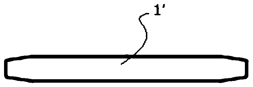
technical field [0001] The invention relates to a manufacturing process of wind power blades, in particular to a load-bearing structure for wind power blades and a preparation method thereof. Background technique [0002] As the length of the blade increases, the load on the main girder is also increasing, and the requirements for the main girder are also getting higher and higher. [0003] Fiber-reinforced resin composite pultruded sheet (hereinafter referred to as "sheet") has the advantages of excellent mechanical properties and simple processing methods. Using sheets and sheet stacks as reinforced structural parts (such as blade main beams) is an important technology in the design of large blades in the wind power field. train of thought. [0004] like Figure 1a As shown, the cross-sectional shape of the pultruded plate 1' in the wind power blade in the prior art is usually rectangular. Such pultruded sheets 1' are stacked to form sheet structures, such as Figure 1b...

Claims


Application Information

Patent Timeline
Patent Type & Authority Applications(China)
IPC IPC(8): F03D80/00F03D9/25B29C70/36B29C70/46
CPCB29C70/36B29C70/46F03D9/25F03D80/00Y02E10/72
Inventor 张振国王国军金孝龙
Owner SHANGHAI ELECTRIC WIND POWER GRP CO LTD
Learn More