Maneuvering target multi-frame detection tracking method based on linear pseudo-measurement model

A maneuvering target and pseudo-measurement technology, which is applied in radio wave measurement systems, radio wave reflection/re-radiation, measurement devices, etc., can solve the problem of low estimation accuracy of target maneuvering characteristics, no estimation model for historical information, and easy There are problems such as model adaptation, to achieve high maneuvering target detection and tracking performance, to solve the effect of maneuvering target model mismatch, and to avoid calculation costs

Active Publication Date: 2020-06-09
UNIV OF ELECTRONIC SCI & TECH OF CHINA
View PDF12 Cites 4 Cited by
  • Summary
  • Abstract
  • Description
  • Claims
  • Application Information

AI Technical Summary

Problems solved by technology

However, it only gives a heuristic calculation method of acceleration without establishing a complete theoretical model, resulting in low accuracy of target maneuver characteristics estimation and poor algorithm robustness; in addition, the calculation of the possible state transition area after the CS model is introduced There is no specific formula derivation, and the calculation complexity of the algorithm is not considered
A multi-frame detection and tracking algorithm based on the CS model is given in the patent "Multi-frame Detection-Before-Tracking Method for Maneuvering Targets Applicable to Pulse Doppler Radar, CN105974402B"; but only an empirical method is given for the estimation of acceleration value, and does not establish an estimation model for historical information, resulting in low estimation accuracy of the algorithm and prone to model adaptation problems
Therefore, none of the above methods can really effectively solve the problem of maneuvering targets in the multi-frame joint detection and tracking algorithm.

Method used


Image

  • Maneuvering target multi-frame detection tracking method based on linear pseudo-measurement model
  • Maneuvering target multi-frame detection tracking method based on linear pseudo-measurement model
  • Maneuvering target multi-frame detection tracking method based on linear pseudo-measurement model

Examples


Embodiment Construction

[0018] In order to describe content of the present invention conveniently, at first the following terms are explained:

[0019] Term 1: Iterative accumulation

[0020] The multi-frequency and multi-period accumulation process is repeated, and the result of each accumulation is used as the initial value of the next accumulation.

[0021] Term 2: Dimensional Search for Maneuvering Targets

[0022] For the maneuvering target problem, the approximate description of the maneuvering target motion can be achieved by increasing the dimension of the target state space, where the higher the dimension, the more accurate the described target motion.

[0023] Term 3: Augmented State Vector

[0024] On the basis of the existing low-dimensional state vector, by introducing higher-dimensional target state information (such as: velocity, acceleration or higher-order variables, etc.), the new state vector formed becomes the augmented target state vector.

[0025] Term 4: Target detection pro...


PUM


Abstract

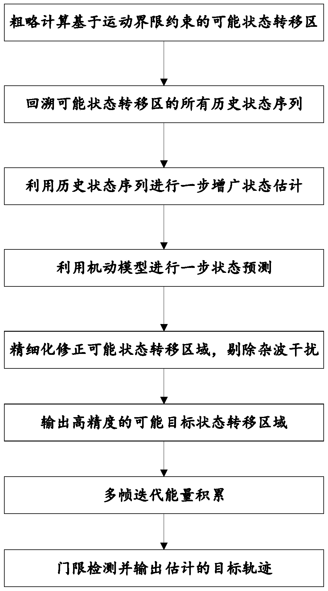
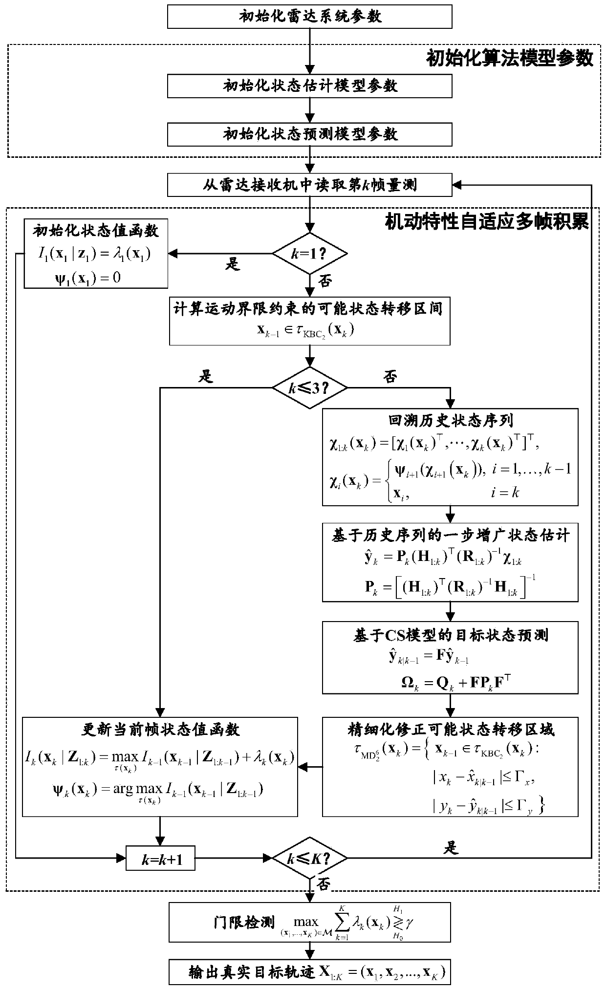
The invention discloses a maneuvering target multi-frame detection tracking method based on a linear pseudo-measurement model, is applied to the technical field of radar target detection and tracking,and aims to solve the problems that a traditional maneuvering target multi-frame detection tracking method based on motion boundary constraint is low in tracking precision and poor in detection performance and the huge calculation cost problem of maneuvering target tracking by increasing the dimensionality of the search state space in the prior art. Historical information is used as a priori multi-stage joint optimization idea, firstly, a linear pseudo-measurement model is established according to historical information to estimate the motion information amount of a high-order target; then, amaneuvering target state transition model is introduced to model target maneuvering characteristics, then, the size of the multi-frame accumulation possible state transition interval is adaptively adjusted according to the established target maneuvering model, and finally a complete target detection tracking trajectory is outputted.

Description

technical field [0001] The invention belongs to the technical field of radar target detection and tracking, and in particular relates to a multi-frame joint target detection and tracking technology under the condition of high maneuvering targets. Background technique [0002] Active radar systems often face the effective detection requirements of weak targets and high maneuvering targets in complex environments. The traditional algorithm of single-frame detection and then associated tracking of maneuvering targets has information loss in the process of single-frame threshold detection, resulting in serious loss of weak targets, poor track continuity, and many false tracks in the follow-up tracking processing results, which seriously restricts the radar. System detection performance. [0003] Track-before-detection (TBD), as an effective weak object detection and tracking technology, has become a key research object in the field of object detection and tracking. Different f...

Claims


Application Information

Patent Timeline
IPC IPC(8): G01S13/72G06F17/10
CPCG01S13/723G06F17/10
Inventor 易伟李武军杨琪张鹏辉刘克柱彭琪芸曾凯文耀毅孔令讲杨晓波
Owner UNIV OF ELECTRONIC SCI & TECH OF CHINA
Why Eureka
Try Eureka