
Butting positioning tool for arc striking and quenching plates and positioning butting method thereof

A technology for igniting and extinguishing arc plates and positioning tooling, applied in welding protection devices, welding/welding/cutting items, manufacturing tools, etc. Inconsistent quality stability, unsatisfactory use convenience, etc., to achieve the effect of convenient positioning and assembly, compact structure, efficient and fast pressing action

Pending Publication Date: 2020-06-12
陕西戴爱盟德电子科技有限公司
View PDF2 Cites 17 Cited by
  • Summary
  • Abstract
  • Description
  • Claims
  • Application Information

AI Technical Summary

Problems solved by technology

However, this device can only replace the manual operation of lifting the arc plate and closing the arc plate to the pipe end; the most critical coaxial alignment between the arc plate and the pipe end and the close operation of the arc plate and the pipe end still need to be completed manually; therefore The use of this device has not fundamentally solved the technical problems of automatic alignment between the arc extinguishing plate and the pipe end, as well as automatic tightening and clamping, and the problem of inconsistent welding quality stability still exists
Publication No. CN110125520A discloses a clamping device for extinguishing arc plates; this device only solves the technical problem of clamping arc plates with different thicknesses, but does not solve the alignment of arc plates and pipe ends and the alignment of arc plates. The technical problem of closeness to the pipe end; not only that, the clamping of the arc plate of the device is realized by bolts; the efficiency of the clamping operation is low; the convenience of the device is not ideal

Method used


Image

  • Butting positioning tool for arc striking and quenching plates and positioning butting method thereof
  • Butting positioning tool for arc striking and quenching plates and positioning butting method thereof
  • Butting positioning tool for arc striking and quenching plates and positioning butting method thereof

Examples


Embodiment Construction

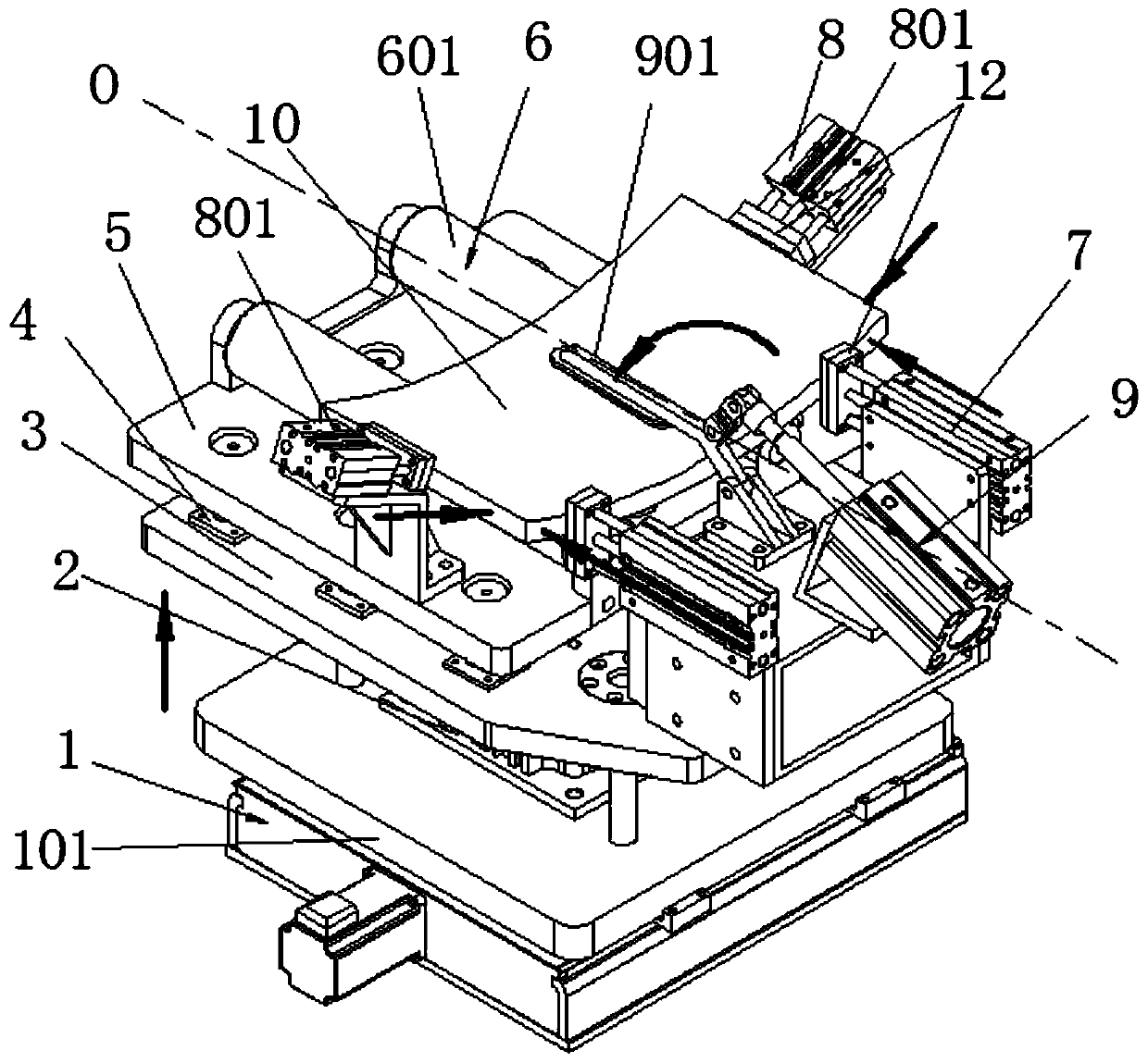
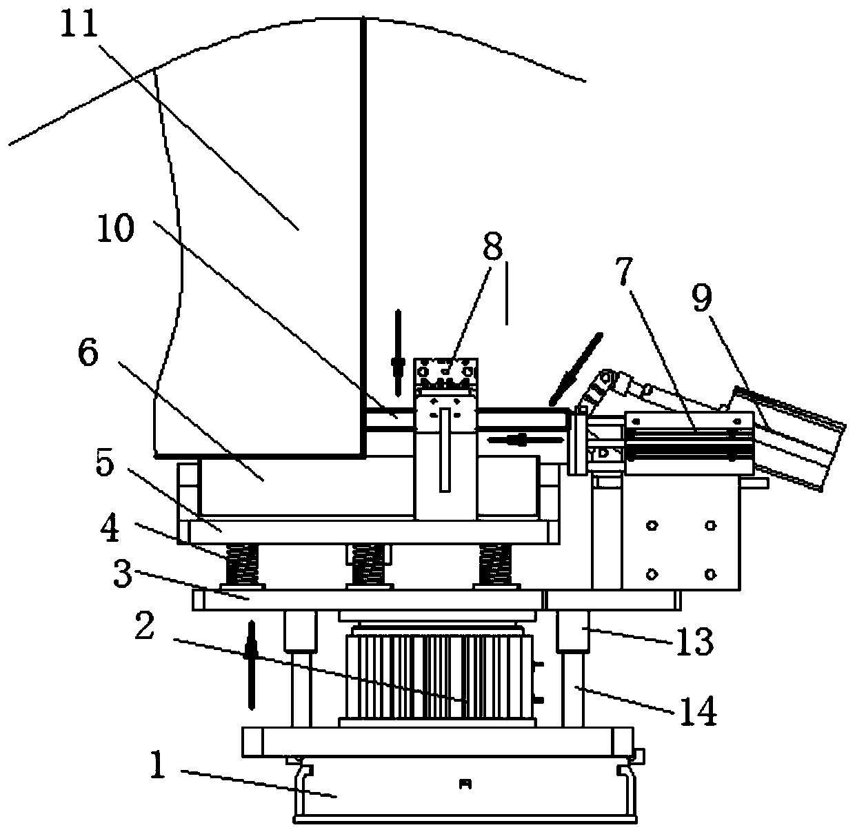
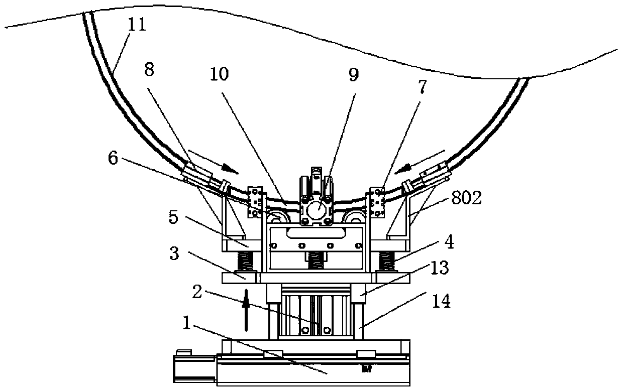
[0033] Attached below Figure 1-8 Specific examples of the present invention are described. It should be understood that the embodiments described below are only illustrative rather than specific limitations on the present invention.

[0034] The following examples facilitate a better understanding of the present invention, but do not limit the present invention. The experimental methods in the following examples are conventional methods unless otherwise specified. The test components and materials used in the following examples are commercially available unless otherwise specified. The implementation of the control circuit in the following embodiments is a conventional control method unless otherwise specified.

[0035] In the present invention, unless stated otherwise, it should be understood that the terms "center", "upper", "lower", "front", "rear", "left", "right", "vertical The orientations or positional relationships indicated by "straight", "horizontal", "top", "bo...


PUM


Abstract

The invention provides a butting positioning tool for arc striking and quenching plates and a positioning butting method thereof. The tool is provided with a translation sliding table for aligning thetool and a pipe end; the translation sliding table drives a lifting platform to lift through a vertical lifting cylinder, the lifting platform is provided with a loading platform in parallel throughflexible self-adaptive assemblies, the loading platform is provided with profiling roller assemblies for aligning the arc plates and the pipe end, the loading platform is provided with a pair of positioning and clamping mechanisms, and the lifting platform is provided with a pair of horizontal pushing mechanisms and a pressing mechanism; and automatic lifting, pushing, approaching, clamping, centering, fixing, abutting and downward pressing and aligning operations of the arc places with respect to the pipe end are realized through the mechanisms. The manpower is replaced, and the automatic plate aligning and positioning operation before welding of the arc striking and quenching plates is realized in a high efficiency, labor-saving and accurate mode.

Description

technical field [0001] The invention belongs to the technical field of arc welding auxiliary tooling for operation and transportation, and in particular relates to a docking and positioning tool for ignition and extinguishing arc plates and a positioning and docking method thereof. Background technique [0002] In the submerged arc welding production process of straight seam or spiral welded seam steel pipe, the arc ignition and arc extinguishing stages of submerged arc welding are prone to slag inclusions and pore welding quality defects; in order to improve the welding quality, it is necessary to start and At the end, weld an arc-extinguishing plate for extension to ensure the consistency of the weld seam quality of the steel pipe; and after the welding is completed, cut off the arc plate to ensure the welding quality of the steel pipe. At present, the preparatory work before welding the extinguishing arc plate and the pipe end requires manual lifting of the plate, manual ...

Claims


Application Information

Patent Timeline
Patent Type & Authority Applications(China)
IPC IPC(8): B23K9/00B23K9/28B23K9/32B23K101/06B23K103/04
CPCB23K9/00B23K9/287B23K9/321B23K2101/06B23K2103/04
Inventor 张瑾宇王林军尹志远王刚陈铭
Owner 陕西戴爱盟德电子科技有限公司
Learn More