Printing roller structure and installation method

A printing roller and sleeve technology, which is applied in printing, printing machines, rotary printing machines, etc., can solve the problems of high storage environment requirements, difficult loading and unloading, excessive jumping of anilox rollers or plate rollers, etc., and achieve the storage environment. The effect of low requirements, low processing difficulty and high processing precision

Pending Publication Date: 2020-06-12
上海鸣谦印刷器材有限公司
View PDF0 Cites 0 Cited by
  • Summary
  • Abstract
  • Description
  • Claims
  • Application Information

AI Technical Summary

Problems solved by technology

[0003] Since the material of the elastic foam layer 5 used in the air expansion roller 1 is soft, the influence of the centrifugal force during high-speed rotation will often cause the anilox roller or plate roller to jump too much, which will affect the printing quality; and limited by the processing conditions, the sleeve 2 It is difficult to process; the material is also easily deformed by the influence of temperature and humidity, which often leads to the situation that the inflatable shaft cannot be removed or put on, and has high requirements for the storage environment; while the other integral roller 6 is The manufacturing cost is too high, the weight is heavier than the sleeve roller, the loading and unloading is difficult, and the operation is unsafe

Method used


Image

  • Printing roller structure and installation method
  • Printing roller structure and installation method
  • Printing roller structure and installation method

Examples


Embodiment Construction

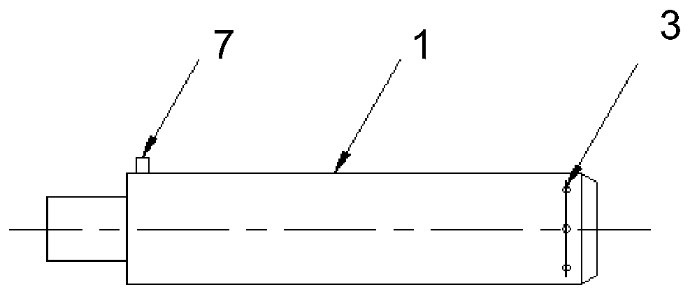
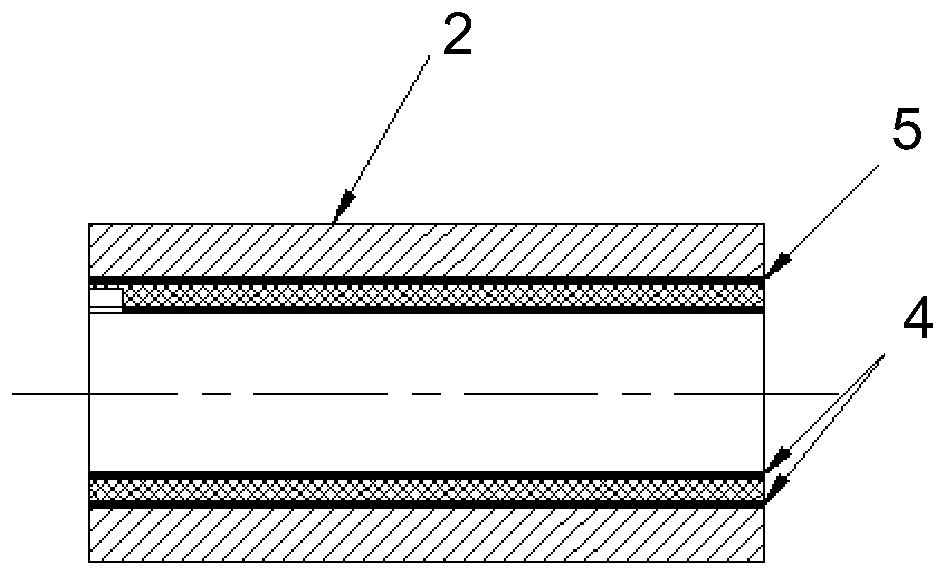
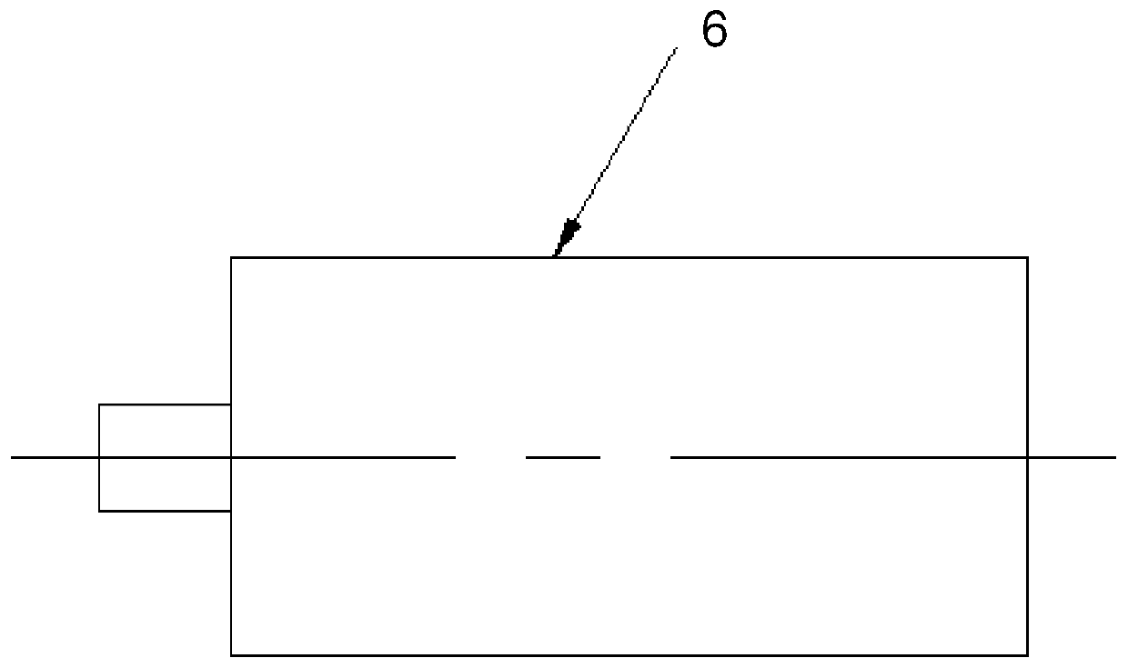
[0024] Printing cylinder structure of the present invention such as Figure 4 ~ Figure 6 As shown, it is the same as the prior art in that it also includes a shaft body 10 with a positioning pin 11 and a sleeve body 13 with an inner hole 12, the inner hole 12 also has a card slot 14, and the sleeve body 13 passes through the inner hole 12 is sheathed on the shaft body 10, and fits with the slot 14 through the positioning pin 11. Different from the prior art, the shaft body 10 has a hydraulic expansion mechanism, and a hydraulic expansion ring 15 is provided on the shaft body 10, and a corresponding hard alloy ring 16 is also provided in the inner hole 12 of the sleeve body 13, and the shaft body 10 is provided with a hydraulic expansion ring 15. The body 10 is in clearance fit with the inner hole 12, and the hydraulic expansion ring 15 and the alloy ring 16 are braced radially.

[0025] As an embodiment, the hydraulic expansion ring 15 has a pair, which are respectively provi...


PUM


Abstract

The invention discloses a printing roller structure. The printing roller structure comprises a shaft body with a positioning pin and a sleeve body with an inner bore, the inner bore is further provided with a clamping groove, the sleeve body sleeves the shaft body through the inner bore and is matched with the clamping groove through the positioning pin, a hydraulic expansion ring is further arranged on the shaft body, a corresponding alloy ring is further arranged in the inner bore, the shaft body is in clearance fit with the inner bore, and the hydraulic expansion ring and the alloy ring areradially braced. The invention further discloses an installation method of the printing roller structure. The hydraulic expansion ring is adopted to be matched with the alloy ring, so that the bounceof a top circle of a sleeve roller is eliminated to the greatest extent, the machining difficulty is low, the machining precision is high, the printing roller structure is difficult to transform affected by air temperature and dryness and humidity, the situation that a sleeve does not be taken out and does not sleeve the shaft is reduced to the greatest extent, and the requirement on the storageenvironment is further low.

Description

technical field [0001] The invention belongs to the field of printing equipment, and in particular relates to a printing roller structure and an installation method. Background technique [0002] Existing anilox rolls or plate rolls mainly have two structures, one is an air expansion roll, and the other is an integral roll. figure 1 It is the air expansion roller 1, and the sleeve 2 (see figure 2 ), the air hole 3 is ventilated, and the glass fiber lining 4 of the sleeve 2 is expanded. After the sleeve 2 is completely installed, the air pressure is removed. Roll 1. figure 1 Middle 7 is positioning pin. image 3 It is an integral roller 6, which needs to be disassembled and assembled as a whole when changing. [0003] Since the material of the elastic foam layer 5 used in the air expansion roller 1 is soft, the influence of the centrifugal force during high-speed rotation will often cause the anilox roller or plate roller to jump too much, which will affect the printing ...

Claims


Application Information

Patent Timeline
Patent Type & Authority Applications(China)
IPC IPC(8): B41F13/20
CPCB41F13/20
Inventor 李雄刘扬
Owner 上海鸣谦印刷器材有限公司
Why Eureka
Try Eureka