Epoxy terrace construction robot

A technology of epoxy flooring and robots, applied in the field of painting, can solve problems such as low efficiency, high cost, and repetitive labor

Pending Publication Date: 2020-06-12
HANGZHOU ZHONGWEI PHOTOELECTRICITY
View PDF0 Cites 5 Cited by
  • Summary
  • Abstract
  • Description
  • Claims
  • Application Information

AI Technical Summary

Problems solved by technology

Continue a smart device to solve these jobs with harsh environment, repetitive labor, low efficiency, h

Method used


Image

  • Epoxy terrace construction robot
  • Epoxy terrace construction robot
  • Epoxy terrace construction robot

Examples


Embodiment 1

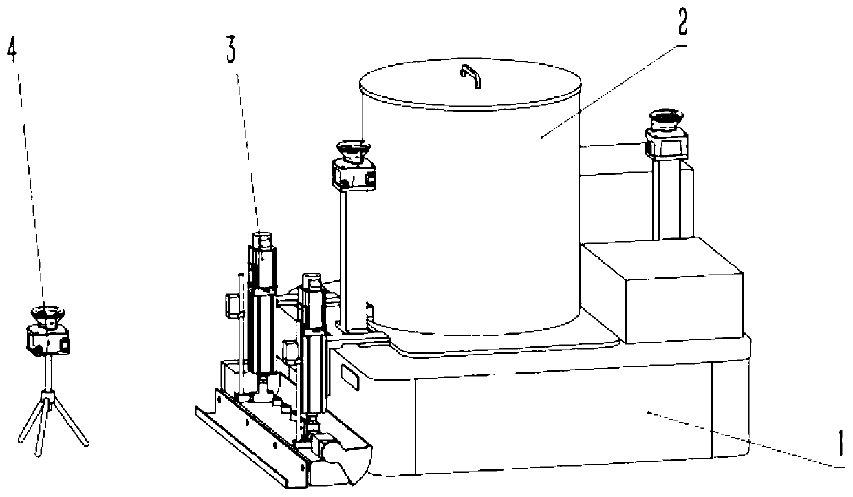
[0030] like figure 1 An epoxy floor construction robot shown includes a robot-driven chassis 1, a feeding device 2, an intermediate coating assembly 3, a primer surface coating assembly 5, a bottom spray surface spray assembly 6, a feeding device 2, and an intermediate coating assembly 3. Including the primer and surface coating assembly 5, the bottom spray surface spray assembly 6 is installed on the robot driving chassis 1, and is electrically connected with the robot driving chassis 1. The robot-driven chassis 1 is the drive, navigation, control, planning, and power supply components of the epoxy floor construction robot, and has the functions of walking, path planning, navigation, coordinated control, power supply and distribution, and the like. The feeding device 2 is used to feed and control the feeding for the epoxy floor construction robot. The feeding device 2 is used to load the spraying material. The feeding device 2 is installed on the robot driving chassis 1 and i...

Embodiment 2

[0043] A kind of epoxy floor construction robot as shown in embodiment 1, its difference is only, one or more in the intermediate coating assembly 3, the primer surface coating assembly 5, the bottom spray surface spray assembly 6 are installed on the robot drive chassis 1 indivual. By installing the intermediate coating assembly, primer surface coating assembly, and bottom spraying surface spraying assembly on the robot-driven chassis, there is no need to replace the spraying parts when changing the spraying material or process, ensuring the continuity and convenience of material spraying and saving replacement time.

Embodiment 3

[0045] An epoxy floor construction robot as shown in Embodiment 1, the only difference is that the epoxy floor construction robot also includes a laser emitter assembly 4 for detecting and feeding back the flatness of the bottom surface, and the laser emitter assembly 4 Placed in front of the running track of the epoxy floor construction robot. By setting the laser emitter assembly 4, the epoxy floor construction robot can automatically complete the adjustment according to the flatness of the bottom surface.


PUM


Abstract

The invention discloses an epoxy floor construction robot. The robot comprises a robot driving chassis, a feeding device, a floating coat assembly, a laser transmitter assembly, a bottom coat and surface coat assembly and a bottom spray and surface spray assembly, the bottom spray and surface spray assembly, the feeding device, the floating coat assembly, the bottom coat and surface coat assemblyand the bottom spray and surface spray assembly are installed on robot driving chassis, and the motor is electrically connected with the robot driving chassis. The robot driving chassis is a driving,navigation, control, planning and power supply assembly and has the functions of driving walking, path planning, navigation, coordination control and electric quantity supply and distribution; the feeding device is used for coordinately controlling the discharge amount of the coating slurry in the feeding device; and the middle coating assembly, the bottom coating and top coating assembly and thebottom spraying and top spraying assembly are used for spraying slurry. The epoxy terrace construction robot greatly reduces injuries to workers, improves the product quality and has the advantages ofbeing low in cost, high in safety, high in recognition precision and high in efficiency.

Description

technical field [0001] The invention relates to the field of painting, in particular to an epoxy floor construction robot. Background technique [0002] Epoxy floor is a common ground floor. Due to its excellent performance and reasonable cost, it is generally used in production workshops, underground garages, and family houses. The implementation process of epoxy floor roughly includes base layer grinding—primer coating—drying and curing—scraping middle coating—drying and curing—middle coating grinding—scraping the second middle coating—drying and curing—middle coating grinding— Apply topcoat—dry and solidify—apply two coats of topcoat. Among them, there are grinding machines in the grinding market, which can effectively reduce labor and improve efficiency. However, in the processes of primer, intermediate coating slurry, and top coating, all are manual operations. The primer coating process generally uses the paint to be splashed on the ground and scraped or rolled with ...

Claims


Application Information

Patent Timeline
IPC IPC(8): E04F21/24
CPCE04F21/24
Inventor 叶欣张江水
Owner HANGZHOU ZHONGWEI PHOTOELECTRICITY
Why Eureka
Try Eureka