Heat exchanging structure with corresponding features as well as heat exchanger and application method thereof

A technology of heat exchange structure and corresponding characteristics, applied in the field of new symmetrical heat exchange structure, can solve problems such as application methods that are not involved, and achieve the effects of facilitating large-scale automated production, good economy, and strong practicability

Active Publication Date: 2020-06-12
湖南雅立科技开发有限公司
View PDF6 Cites 4 Cited by
  • Summary
  • Abstract
  • Description
  • Claims
  • Application Information

AI Technical Summary

Problems solved by technology

[0011] The patent document, heat exchange structure CN103994676B, discloses a new type of heat transfer structure with heat recovery function based on double air channels of finned tubes. However, this document does not give a detailed description of the structure of the finned tube with symmetrical features. The structure described in this patent is only a part of the finned tube heat exchange structure, and does not involve various application methods, including defrosting, etc. , in fact, the finned tube heat exchange structure has a very wide range of changes and applications, and its application potential is huge

Method used


Image

  • Heat exchanging structure with corresponding features as well as heat exchanger and application method thereof
  • Heat exchanging structure with corresponding features as well as heat exchanger and application method thereof
  • Heat exchanging structure with corresponding features as well as heat exchanger and application method thereof

Examples


Embodiment Construction

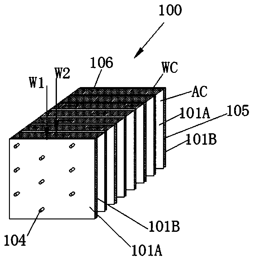
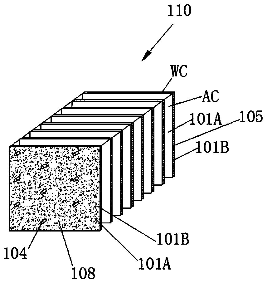
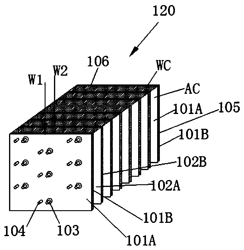
[0093] The invention provides a heat exchange structure with corresponding features, which is composed of a plurality of fins, sealing bodies and structural tubes, the structural tubes pass through the fins and fix the fins, and the fins are sealed around by the sealing body. The sealing body is provided with an air inlet and an air outlet to form passages, and the passages with the same positions of the air inlet and the air outlet are the same group of passages. Functional elements are arranged in the channel, on the channel wall, that is, on the fins, or through the channel, or through the fins, and have at least one of the following corresponding features:

[0094] (1) There are two sets of corresponding heat exchange tubes and fins, the heat exchange tubes run through the fins, and the corresponding heat exchange tubes and fins are fixedly connected.

[0095] (2) There are corresponding two sets of channels, and the two sets of channels are respectively used as auxiliary ...


PUM


Abstract

The invention provides a heat exchanging structure with corresponding features. The heat exchanging structure is composed of a plurality of fins, a sealing body and a structural pipe and at least hasone of the following corresponding features: the heat exchanging structure is provided with two groups of corresponding heat exchanging pipes and fins, the heat exchanging pipes penetrate through thefins, and the corresponding heat exchanging pipes are fixedly connected with the fins; or the heat exchanging structure is provided with two groups of corresponding passages and the two groups of passages serve as an auxiliary passage and a gas passage separately; or functional elements are symmetrically arranged; or the functional elements comprise TEC elements to be symmetrically switched; or the heat exchanging structure is provided with heat exchanging pipes capable of symmetrically switching the flow directions or switching between flow break and open flow; or the heat exchanging structure is provided with symmetrically arranged heat recovery sections, and each of the heat recovery sections is composed of two adjacent passages. Application of the heat exchanging structure comprises defrosting, heat regeneration, air sterilization and disinfection, waste heat recovery, refrigeration and heating, power generation, solar energy utilization, energy storage and the like. The heat exchanging structure is economical and reliable, efficiently saves energy, can be used for traditional air treatment, and can guide out a new application field to generate remarkable economic and energy-saving benefits and environmental and social benefits.

Description

technical field [0001] The present invention relates to a new type of symmetrical heat exchange structure, in particular to a new type of symmetrical heat exchange structure based on finned tubes and its heat exchange device and application. Its applications include defrosting, heat recovery, air sterilization, waste heat recovery, refrigeration Heating, power generation, solar energy utilization and energy storage, etc. Background technique [0002] As a compact and efficient heat exchange device, the finned tube heat exchanger is widely used in various equipment related to air treatment, including air conditioning, refrigeration, heating, dehumidification, drying and water production equipment, etc. [0003] Finned tube heat exchangers, especially expanded tube finned tube heat exchangers, have simple and mature production process, high degree of equipment automation and low manufacturing cost, which is the best choice in the field of air treatment. Although the technolog...

Claims


Application Information

Patent Timeline
Patent Type & Authority Applications(China)
IPC IPC(8): F28D1/053F28D20/02F28F1/32B01D53/00B01D53/26A61L9/00A61L9/16
CPCA61L9/00A61L9/16A61L2209/14A61L2209/22B01D53/005B01D53/261F28D1/053F28D20/021F28F1/32Y02E60/14
Inventor 袁一军叶立英
Owner 湖南雅立科技开发有限公司
Why Eureka
Try Eureka