
Optical modules and electronic equipment

A technology of optical modules and light sources, which is applied in the field of virtual imaging, can solve problems such as the difficulty in meeting the miniaturization design of electronic equipment and the large size of eye tracking modules, and achieve good imaging quality, meet miniaturization design, and reduce size.

Active Publication Date: 2022-04-22
INTERFACE TECH CHENGDU CO LTD +2
View PDF21 Cites 0 Cited by
  • Summary
  • Abstract
  • Description
  • Claims
  • Application Information

AI Technical Summary

Problems solved by technology

[0003] Based on this, it is necessary to provide an optical module and an electronic device for the problem that the size of the current eye tracking module is large and it is difficult to meet the miniaturization design of electronic equipment.

Method used


Image

  • Optical modules and electronic equipment
  • Optical modules and electronic equipment
  • Optical modules and electronic equipment

Examples


Embodiment Construction

[0028] In order to facilitate the understanding of the present invention, the present invention will be described more fully below with reference to the associated drawings. Preferred embodiments of the invention are shown in the accompanying drawings. However, the present invention can be embodied in many different forms and is not limited to the embodiments described herein. On the contrary, the purpose of providing these embodiments is to make the disclosure of the present invention more thorough and comprehensive.

[0029] It should be noted that when an element is referred to as being “fixed” to another element, it can be directly on the other element or there can also be an intervening element. When an element is referred to as being "connected to" another element, it can be directly connected to the other element or intervening elements may also be present. The terms "inner", "outer", "left", "right" and similar expressions are used herein for the purpose of descripti...


PUM

PropertyMeasurementUnit
thicknessaaaaaaaaaa
thicknessaaaaaaaaaa

Abstract

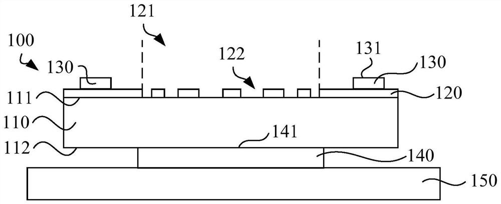
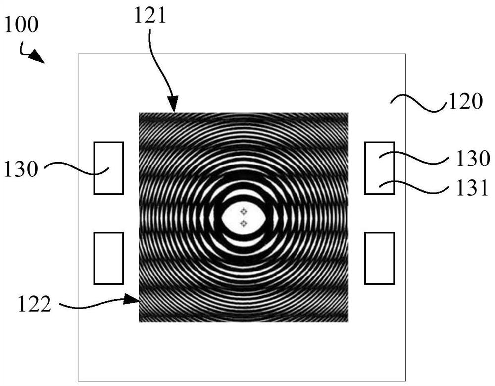
The invention relates to an optical module and electronic equipment including the above optical module. The above-mentioned optical module includes a substrate, a mask layer and a light source. The substrate has a light incident surface. The photomask layer is arranged on the light incident surface, and the photomask layer is provided with a plurality of diffraction slits to form a light incident area, and the geometric center of the light incident area points to the In the direction of the edge, the area of ​​the diffraction slit decreases gradually. The light source has a light emitting surface, the light source is arranged on the light incident surface and is spaced from the light incident area, and the light emitting surface is arranged away from the light incident surface. The size of the above-mentioned optical module is small, which can meet the requirements of miniaturization design of electronic equipment, and has good imaging quality at the same time.

Description

technical field [0001] The invention relates to the technical field of virtual imaging, in particular to an optical module and electronic equipment. Background technique [0002] In virtual imaging electronic devices such as virtual reality (Virtual Reality, referred to as VR) equipment, augmented reality (Augmented Reality, referred to as AR) equipment, and mediated reality (Mediated Reality, referred to as MR) equipment, it is usually necessary to configure an eye tracking module. To track the movement of human eyeballs, and change the position and angle of the image according to the movement of human eyeballs, so as to make people feel immersive. However, the current eye tracking module usually needs to be equipped with a light source and a lens group. The light source emits light to the human eyeball, and the lens group processes the light reflected from the human eyeball. Requirements for the miniaturization design of electronic equipment. Contents of the invention ...

Claims


Application Information

Patent Timeline
Patent Type & Authority Patents(China)
IPC IPC(8): G02B27/00
CPCG02B27/0093
Inventor 王世育
Owner INTERFACE TECH CHENGDU CO LTD
Learn More