Energy-saving cantilever single winch and working method thereof

A single stranding machine and cantilever technology, which is applied in the manufacture of electrical components, circuits, cables/conductors, etc., can solve the problems of heavy weight and consume more energy, and achieve the effect of reducing the difficulty of operation, realizing semi-automatic production and easy assembly.

Pending Publication Date: 2020-06-12
JIANGSU HANDING MACHINERY
View PDF1 Cites 0 Cited by
  • Summary
  • Abstract
  • Description
  • Claims
  • Application Information

AI Technical Summary

Problems solved by technology

In order to ensure the strength of the cantilever plate, most of the existing cantilever plates are made of steel, which is relatively thick and consumes more energy when rotating

Method used


Image

  • Energy-saving cantilever single winch and working method thereof
  • Energy-saving cantilever single winch and working method thereof
  • Energy-saving cantilever single winch and working method thereof

Examples


Embodiment 1

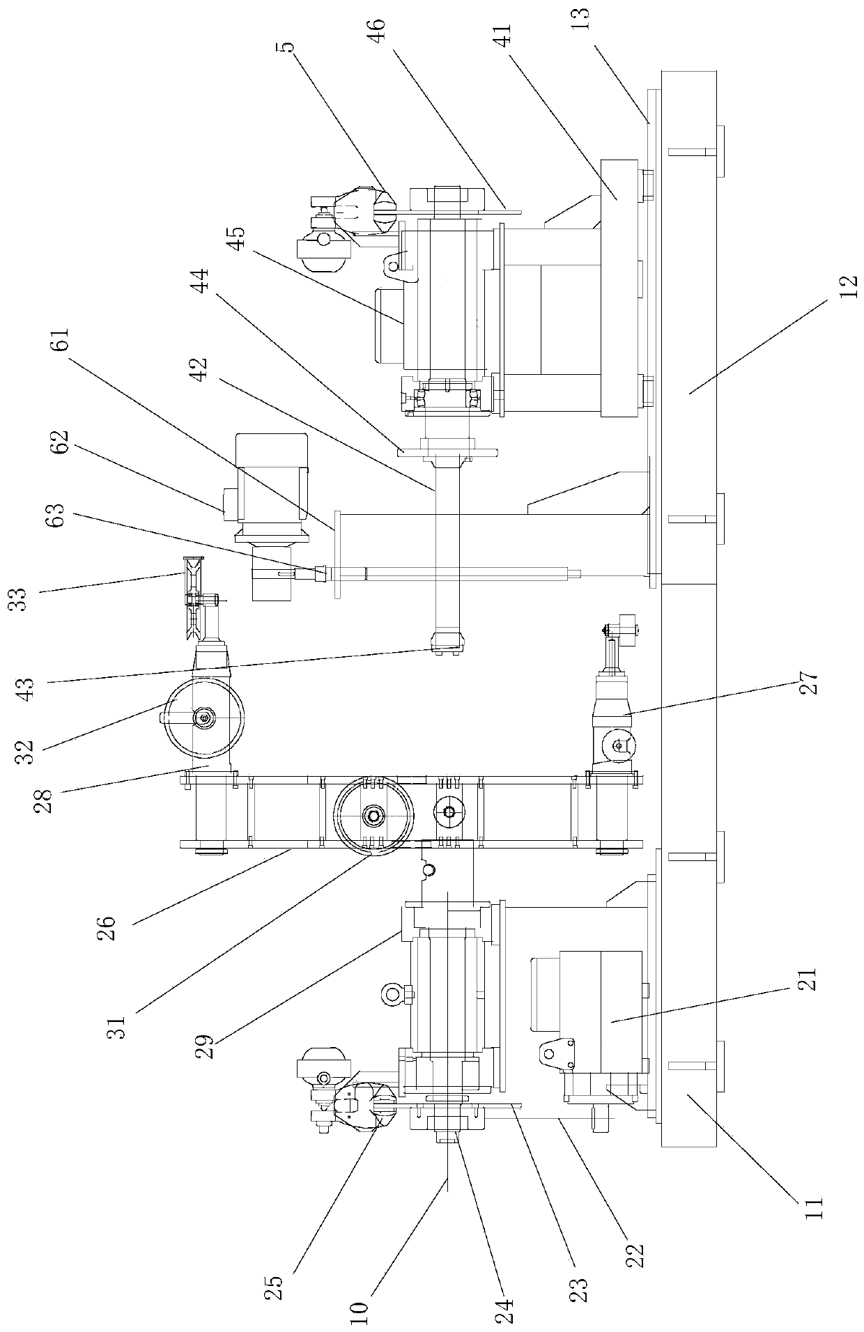
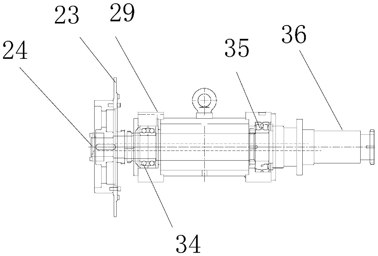
[0037] Example 1 as figure 1 As shown, the energy-saving cantilever single twisting machine of the present embodiment includes a fixed box body 11, a hollow main shaft 24, a movable box body 12, a sliding seat 41, a take-up main shaft 42, and a pallet lifting mechanism, and the main shaft motor is arranged on the fixed box body 11. 21 and the main shaft support, the main shaft bearing seat 29 is set on the main shaft support, as image 3As shown, the main shaft bearing seat 29 rotates and cooperates with the tail of the main shaft 24 through the single-row angular joint ball bearing 34, and the main shaft bearing seat 29 rotates and cooperates with the front part of the main shaft 24 through the self-aligning roller bearing 35, so that the front and rear of the main shaft 24 end protrudes from the main shaft bearing seat 29, and the main shaft motor 21 is driven and matched with the tail end of the main shaft 24 through the main shaft belt 22, so that the main shaft motor 21 c...

Embodiment 2

[0046] The working method of the above-mentioned energy-saving cantilever single winch comprises the following steps:

[0047] A. The tray 7 is fixedly connected to the screw nut 64 through the guide pin, and the lifting motor 62 is started to lower the tray 7 until the tray bottom plate 72 touches the ground. Motor 62 drives pallet 7 to rise.

[0048] B, start translation motor, drive sliding seat 41 to move by translation screw rod, make take-up shaft 42 insert the center of wire reel, cover wire reel gland 43 and make wire reel and take-up shaft 42 be fixedly connected.

[0049] C. Start the lifting motor 62 to lower the tray 7, so that the wire reel is separated from the tray 7; the cable 10 to be wound is passed through the main shaft 24 and introduced into the first guide wheel 31, the second guide wheel 32, and the third guide wheel 33 in sequence , the cable 10 is introduced into the wire reel by the third guide wheel 33, and the take-up shaft motor 45 and the transla...


PUM


Abstract

The invention relates to an energy-saving cantilever single winch and a working method thereof. The energy-saving cantilever single winch comprises a fixed box body, a main shaft, a movable box body,a sliding seat and a take-up main shaft; the main shaft is rotatably arranged on the fixed box body; a cantilever frame is in transmission fit with the main shaft; the cantilever frame comprises a left vertical plate and a right vertical plate which are arranged in parallel; a plurality of transverse supporting plates are arranged between the left vertical plate and the right vertical plate, the two ends of each transverse supporting plate are fixedly connected with the left vertical plate and the right vertical plate respectively, and main shaft assembling holes are formed in the center of the left vertical plate and the center of the right vertical plate so that the main shaft can extend into the main shaft assembling holes to be fixed. The two ends of the cantilever frame are fixedly provided with a wire arm hand and a balance weight arm hand respectively, and the left vertical plate, the right vertical plate, the transverse supporting plate, the wire arm hand and the balance weightarm hand are aluminum alloy products.

Description

technical field [0001] The invention relates to a device for twisting cables, in particular to an energy-saving cantilever single twisting machine and a working method thereof. Background technique [0002] In the production process of cables, the single-twisting machine is a kind of high-frequency wire, data wire, electronic wire, core wire and multi-strand twisting machine used in HDMI, DP, USB, CAT-7, DVI, ATA, SATA, etc. Wire and cable equipment. Single twisting machines are generally divided into three types: vertical single twisting machine, high-speed cantilever single twisting machine, and high-speed cantilever frame single twisting machine. The existing cantilever single-winch machine has a fast twisting speed. For example, the patent document of the applicant's prior application authorization announcement number CN202196620U and the name of the cantilever single-winch machine relates to a cantilever single-winch machine. The hollow shaft on the top, the pulley co...

Claims


Application Information

Patent Timeline
IPC IPC(8): H01B13/02
CPCH01B13/0207
Inventor 肖小勤
Owner JIANGSU HANDING MACHINERY
Why Eureka
Try Eureka