Load connection identification circuit of switching power supply and multi-port charger

A technology for load connection and circuit identification, applied in battery circuit devices, current collectors, circuit devices, etc., can solve the problems of increasing power loss, the protocol chip cannot judge whether the charger output is connected to the load, reducing system efficiency, etc. Blind zone, avoid hot spots and increase system power loss, improve system efficiency

Pending Publication Date: 2020-06-12
BCD (SHANGHAI) MICRO ELECTRONICS LTD
View PDF0 Cites 1 Cited by
  • Summary
  • Abstract
  • Description
  • Claims
  • Application Information

AI Technical Summary

Problems solved by technology

Therefore, the protocol chip can not only judge whether the power supply port (that is, the output port) of the charger is connected to the load through the signal lines D+, D-, CC1 and CC2, but only by measuring the voltage signals on the VBUS and GND lines in the USB line. or current signal to judge
[0004] In the prior art, most of the switching power supplies on the market adopt the conventional identification circuit of "judging whether the output of the switching power supply is connected to the load by measuring the voltage signal at both ends of the current detection resistor". The schematic diagram is as follows figure 1 shown, however using a current sense resistor set at the

Method used


Image

  • Load connection identification circuit of switching power supply and multi-port charger
  • Load connection identification circuit of switching power supply and multi-port charger
  • Load connection identification circuit of switching power supply and multi-port charger

Examples


Embodiment Construction

[0045] In order to make the purpose, technical solutions and advantages of the embodiments of the present invention clearer, the technical solutions in the embodiments of the present invention will be clearly and completely described below in conjunction with the drawings in the embodiments of the present invention. Obviously, the described embodiments It is a part of embodiments of the present invention, but not all embodiments. Based on the embodiments of the present invention, all other embodiments obtained by persons of ordinary skill in the art without making creative efforts belong to the protection scope of the present invention.

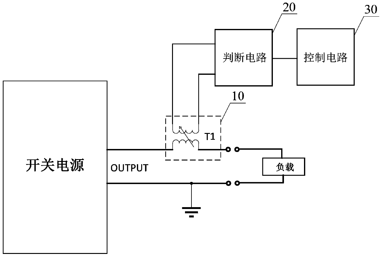
[0046] Please refer to figure 2 , figure 2 It is a structural block diagram of a load connection identification circuit of a switching power supply provided by an embodiment of the present invention. The load connection identification circuit may include:

[0047] The ripple detection circuit 10 is coupled to the output port (OUTPUT) of ...


PUM


Abstract

The invention discloses a load connection identification circuit of a switching power supply. The load connection identification circuit comprises a ripple detection circuit, a judgment circuit and acontrol circuit. Ripple signals of the output port of the switching power supply are detected in a coupling mode through the arrangement of the ripple detection circuit. Whether an output port is connected with a load or not can influence a ripple signal, the detection circuit detects ripple signals of the output port, so that the judgment circuit can judge whether the output port is connected with a load or not according to the detected ripple signals and outputs a judgment result to the control circuit, and the control circuit can recognize the load connection state of the output port and correspondingly control output of the switching power supply. According to the invention, the use of a current sampling resistor is avoided, the increase of heating points and system power loss can be avoided, and the system efficiency is improved. Moreover, the identification blind area of the output current is reduced, and the identification accuracy of load connection is improved. In addition, the invention further discloses a load connection identification circuit of the multi-port charger, and the load connection identification circuit also has the above beneficial effects.

Description

technical field [0001] The invention relates to the technical field of power electronics, in particular to a load connection identification circuit of a switching power supply and a multi-port charger. Background technique [0002] Charger, also known as charging treasure and mobile power supply, is a charging device that provides a stable power supply for electronic equipment containing batteries. It often consists of a stable power supply (providing stable working voltage and sufficient current) plus necessary constant current, limit Voltage and protection functions and other control circuits. [0003] With the rapid popularization of smart devices and smart phones, multi-port intelligent power distribution chargers (ie, multi-port chargers) are increasingly favored by users. Each power supply port of the switching power supply of the multi-port charger is compatible with the fast charging protocol, and only slightly increases the system cost, so the multi-port charger ha...

Claims


Application Information

Patent Timeline
IPC IPC(8): H02J7/00G01R15/18
CPCG01R15/18
Inventor 罗月亮
Owner BCD (SHANGHAI) MICRO ELECTRONICS LTD
Why Eureka
Try Eureka