
Filter stick cutting and section detecting device

A detection device and filter rod technology, which is applied in the fields of application, tobacco, and paper cigarette manufacturing, can solve problems such as inaccurate and reliable detection results, broken cutting sections, and long transmission distances, and achieve compact structure, smooth cross-section, and improved filter rod quality Effect

Pending Publication Date: 2020-06-16
郑州润丰德科技有限公司
View PDF0 Cites 2 Cited by
  • Summary
  • Abstract
  • Description
  • Claims
  • Application Information

AI Technical Summary

Problems solved by technology

However, the existing cutting device and cross-section detection device have complex structures and large volumes, and the transmission distance between them is relatively long, which may easily cause damage to the cutting cross-section, resulting in inaccurate and reliable detection results.
[0003] This shows that the above-mentioned existing filter rod cutting device and cross-section detection device obviously still have inconvenience and defects in structure, method and use, and need to be further improved urgently

Method used


Image

  • Filter stick cutting and section detecting device
  • Filter stick cutting and section detecting device
  • Filter stick cutting and section detecting device

Examples


Embodiment Construction

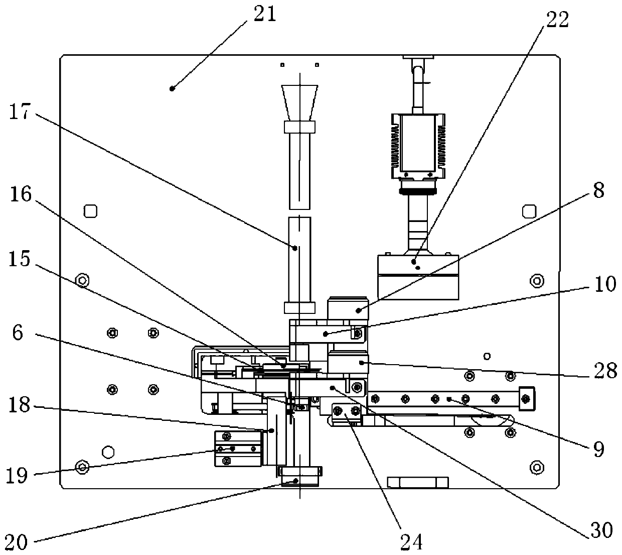
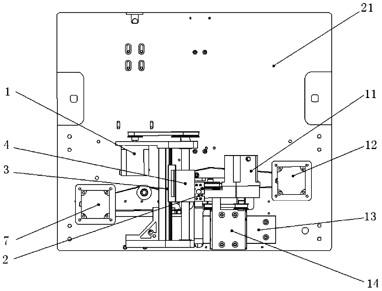
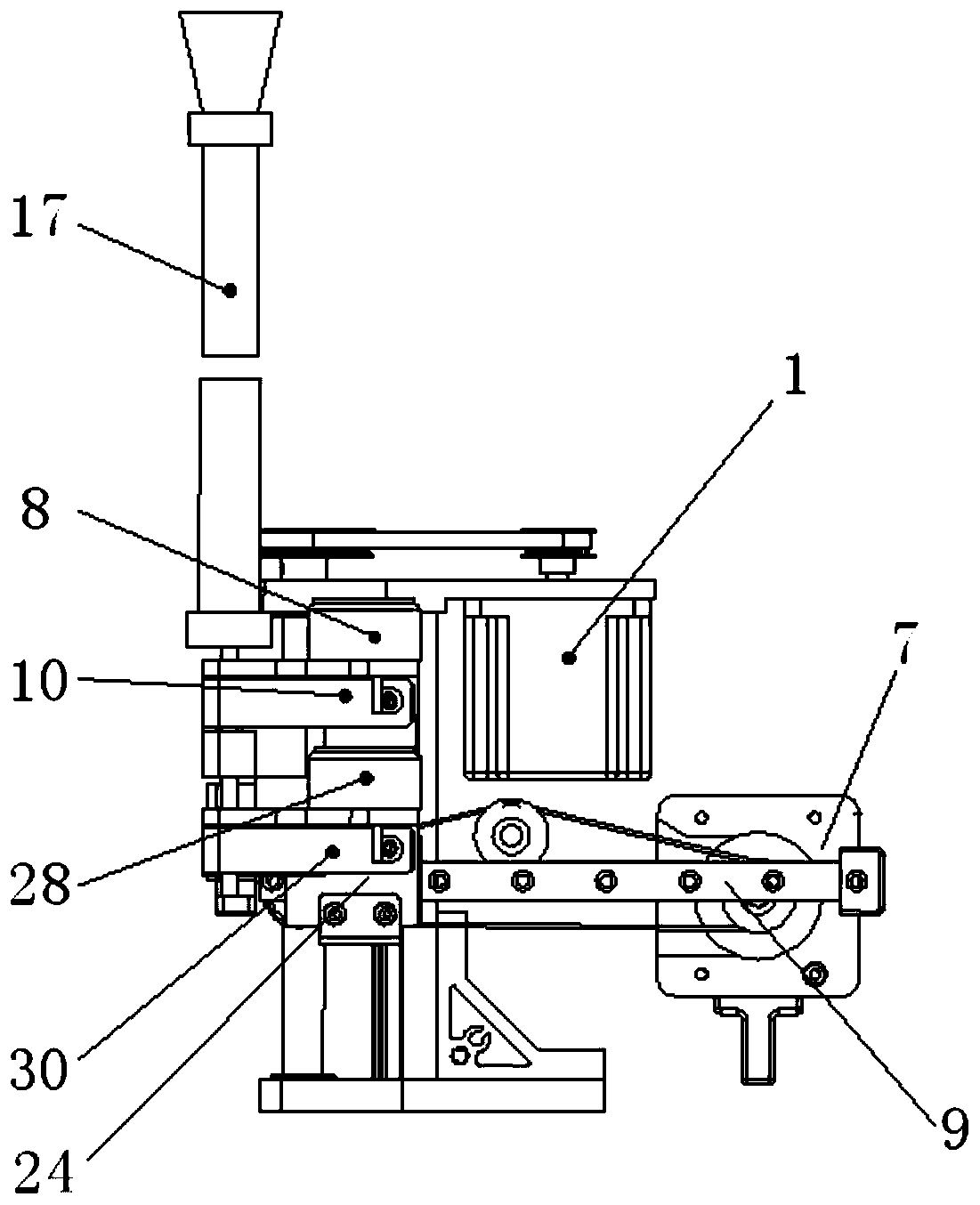
[0032] Refer to attached figure 1 and 2 As shown, the filter rod cutting and cross-section detection device of this embodiment includes a fixed base plate 21 vertically arranged on the ground and a filter rod guide mechanism, a positioning mechanism, a clamping mechanism, a cutting mechanism and a cross-section detection mechanism arranged on the front and rear sides of the base plate 21. mechanism.

[0033] The filter rod guide mechanism includes an upper guide tube 17 and a lower guide tube 18, the upper guide tube 17 is vertically fixed on the upper part of the front side of the base plate 21, and the lower guide tube 18 is vertically and movable left and right arranged on the base plate 21 lower front side. Driven by the first power mechanism, the lower guide pipe 18 can move to a position communicating with the upper guide pipe 17, providing a guide passage for the upper filter rod 23 to fall after cutting. Wherein, the first power mechanism adopts a telescopic air cyl...


PUM


Abstract

The invention discloses a filter stick cutting and section detecting device which comprises a fixed base plate, and a filter stick guide mechanism, a positioning mechanism, a clamping mechanism, a cutting mechanism and a section detecting mechanism which are arranged on the front side surface and the rear side surface of the fixed base plate. The filter stick guide mechanism comprises upper and lower guide pipes, the upper guide pipe is vertically fixed to the upper portion of the front side face of the base plate, and the lower guide pipe is arranged on the lower portion of the front side face of the base plate in a left-right moving mode. A positioning supporting plate of the positioning mechanism can be driven by a second power mechanism to move to the position below the upper guide pipe. The clamping mechanism comprises an upper clamping jaw and a lower clamping jaw, and the lower clamping jaw can be driven by a third power mechanism to move to the position below the image acquisition unit to achieve section detection. A blade of the cutting mechanism cuts the filter stick under the control of a fourth power mechanism. The section detection mechanism detects the section of thefilter stick clamped by the lower clamping jaw through the image acquisition unit. The mechanisms are arranged on the front side face and the rear side face of the base plate, accurate falling, positioning cutting and section detection of the filter stick can be achieved, layout is reasonable, and the structure is compact.

Description

technical field [0001] The invention relates to the technical field of cigarette / filter rod processing and production, in particular to a filter rod cutting and section detection device. Background technique [0002] The existing cigarette / filter rod cutting device cuts the continuous cigarette / filter rod of the cigarette / filter rod forming system, and cuts it into cigarettes / filter rods of required length according to the process requirements. After the cutting is completed, the cigarette / filter rod needs to be transferred to the cross-section detection device for cross-section detection. However, the existing cutting device and cross-section detection device have complex structures and large volumes, and the transmission distance between them is relatively long, which easily causes damage to the cutting cross-section, resulting in inaccurate and reliable detection results. [0003] This shows that the above-mentioned existing filter rod cutting device and section detectio...

Claims


Application Information

Patent Timeline
Patent Type & Authority Applications(China)
IPC IPC(8): A24C5/34A24C5/28
CPCA24C5/28A24C5/3412
Inventor 楚淑青王建芳舒奎武马锋刘菊清寇鹏
Owner 郑州润丰德科技有限公司
Learn More