Gas distribution plate for vibrated fluidized bed

A gas distribution plate, plate body technology, applied in chemical/physical processes, chemical instruments and methods, etc., can solve the problems of large collision probability between particles and cone caps, no guiding function, large resistance loss, etc., to prevent dead beds. generation, good fluidization conditions, enhanced disturbance effect

Active Publication Date: 2020-06-16
TIANJIN UNIV
View PDF16 Cites 0 Cited by
  • Summary
  • Abstract
  • Description
  • Claims
  • Application Information

AI Technical Summary

Problems solved by technology

The inclined-hole gas distribution plate is an optimized form of the direct-flow gas distribution plate. It has a larger air distribution area and has a guiding effect. The guiding direction is adjusted according to the angle of the inclined hole. The disadvantage is that the distribution plate is relatively thick to form the angle of the inclined hole, resulting in loss of resistance. Big
The side-flow gas distribution plate is not easy to leak and clog, and eliminates the generation of dead beds, but the structure is relatively complicated, it is not easy to manufacture, it has no guiding function, and the probability of collision between particles and the cone cap is high

Method used


Image

  • Gas distribution plate for vibrated fluidized bed
  • Gas distribution plate for vibrated fluidized bed
  • Gas distribution plate for vibrated fluidized bed

Examples


Embodiment 1

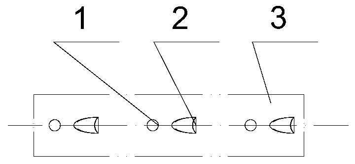
[0048] Figure 8 An arrangement of gas distribution holes is given. Straight holes 1 are arranged in an equilateral triangle with side length L 3 =L 4 =20mm, α=60°, a straight hole 1 is arranged on the opposite side of the opening direction of each ellipsoidal curved surface guide hole 2 with a chamfered angle, and the exit of the ellipsoidal curved surface guide hole 2 with a chamfered angle is to the opposite side of the opening direction The center distance L of the set straight hole 1 2 is 15.5mm. Ellipsoidal surface guide hole with chamfer 2 long L 1 , width B 1 , high H 1 They are 8mm, 5.5mm, and 2mm respectively, and the cutting angle θ is 120°. The matching straight hole 1 has a diameter of 4mm, and the diameter of the straight hole is 0.73 times the width of the guide hole on the ellipsoidal surface with chamfered corners. The plate body 3 has a thickness of 2 mm. use Figure 8 The structure of the gas distribution plate is shown, and the size of the distrib...

Embodiment 2

[0050] Figure 9 A gas distribution plate arrangement is given. The straight holes 1 are arranged in a rectangle, and the distance between the centers of two adjacent straight holes is L 5 =35mm, distance L between two adjacent rows of straight holes 6 = 20mm. A straight hole 1 is arranged on the opposite side of the opening direction of each ellipsoidal curved surface guide hole 2 with a chamfered angle, and the center distance from the exit of the ellipsoidal curved surface guide hole 2 with a chamfered angle to the straight hole 1 set on the opposite side of the opening direction L 2 is 15.5mm. Ellipsoidal surface guide hole with chamfer 2 long L 1 , width B 1 , high H 1 They are 8mm, 5.5mm, and 2.04mm respectively, and the cutting angle θ is 90°. The matching straight hole 1 has a diameter of 5.5mm, and the diameter of the straight hole is 1 time of the width of the guide hole on the ellipsoidal surface with chamfered corners. The plate body 3 has a thickness of 2...

Embodiment 3

[0052] Figure 10 A gas distribution plate arrangement method is given, the straight holes 1 are arranged in a square, and the distance between the centers of two adjacent straight holes is L 5 =35mm, distance L between two adjacent rows of straight holes 6 = 35mm. A straight hole 1 is arranged on the opposite side of the opening direction of each ellipsoidal curved surface guide hole 2 with a chamfered angle, and the center distance from the exit of the ellipsoidal curved surface guide hole 2 with a chamfered angle to the straight hole 1 set on the opposite side of the opening direction L 2 is 15.5mm. Ellipsoidal surface guide hole with chamfer 2 long L 1 , width B 1 , high H 1 They are 8mm, 5.5mm, and 1.31mm respectively, and the cutting angle θ is 165°. The matching straight hole 1 has a diameter of 7mm, and the diameter of the straight hole is 1.27 times the width of the guide hole on the ellipsoidal surface with chamfered corners. The plate body 3 has a thickness ...


PUM


Abstract

The invention relates to a gas distribution plate for a vibrated fluidized bed. The gas distribution plate comprises a straight holes, ellipsoid curved surface guide holes with chamfers and a plate body, the ellipsoid curved surface guide holes with the chamfers and the straight holes are distributed in the plate body at intervals. A straight hole is formed in the opposite side of the opening direction of each ellipsoid curved surface guide hole with the chamfer; and the distance from the ellipsoid curved surface guide holes with the chamfers in the same row to the straight holes opposite to the hole opening direction is smaller than that from the ellipsoid curved surface guide holes to the straight holes in the hole opening direction side. The straight holes are distributed in a triangular and rectangular mode, and the ellipsoid curved surface guide holes with the chamfers are distributed along with the straight holes. By using the gas distribution plate, the gas distribution is moreuniform; not only can the guide be realized, but also the particles can generate a good fluidization state and can stably and continuously flow down; the collision strength and probability of the particles and the distribution plate are reduced; the opening structure is not easy to block and damage, and the number of dead zones of a bed layer can be reduced; disturbance of a gas phase near the surface of the gas distribution plate is enhanced, so that the particles are in full contact with hot air; the structure is simple, and manufacturing is convenient.

Description

technical field [0001] The invention relates to a gas distribution plate, in particular to a gas distribution plate for a vibrating fluidized bed. Background technique [0002] Fluidized bed has good solid fluidity and heat and mass transfer characteristics, so it is widely used in petroleum, chemical industry, energy, environmental protection, pharmaceutical, food processing and other fields. In practical applications, most of the dry materials are non-spherical particles. Compared with spherical particles, non-spherical particles have the characteristics of anisotropy and poor fluidity. At present, there are two ways to increase the fluidity of non-spherical particle materials: one is to use a common fluidized bed with a gas distribution plate with a guiding function, such as an oblique hole gas distribution plate; the other is to use vibratory fluidization The bed relies on the combined action of vibration and gas distribution plates. In an ordinary fluidized bed, air ...

Claims


Application Information

Patent Timeline
IPC IPC(8): B01J8/18B01J8/40
CPCB01J8/40B01J8/1818
Inventor 王晓静苏伟臧明华武宸宇
Owner TIANJIN UNIV
Why Eureka
Try Eureka