
Annular part shaping device

A shaping device and a ring-shaped technology, applied in metal processing equipment, forming tools, manufacturing tools, etc., can solve the problems of difficult to achieve shaping tools, large sintering shrinkage, low work efficiency, etc., achieve a compact overall structure, and solve out-of-roundness Problems, the effect of easy disassembly and removal

Pending Publication Date: 2020-06-16
ANHUI HAOFANG ELECTROMECHANICS
View PDF0 Cites 1 Cited by
  • Summary
  • Abstract
  • Description
  • Claims
  • Application Information

AI Technical Summary

Problems solved by technology

In the shaping process after the metal powder injection molding process, especially when it involves round parts, due to the large sintering shrinkage, there are often out-of-round phenomena. According to the size of the product, the out-of-roundness can reach 0.5mm-1mm. The difficulty of shaping is different from other The shaping of parts generally uses hydraulic presses or manual presses combined with shaping molds for shaping operations. Products with relatively high roundness requirements have a high scrap rate and low work efficiency, especially when the roundness reaches below 0.1mm. It is difficult to achieve with technical shaping tools. In production practice, we accidentally found that the roundness of the traditional two semicircular outer sliders and inner extrusion structure after shaping is within the range of 0.2-0.5mm.

Method used


Image

  • Annular part shaping device
  • Annular part shaping device
  • Annular part shaping device

Examples


Embodiment 1

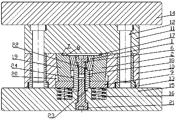
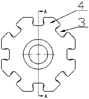
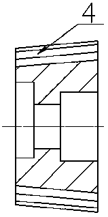
[0021] Embodiment 1: as figure 1 -shown in 4, a kind of annular part shaping device, it comprises base plate 15 and the lower mold base 10 that is fixedly arranged on the base plate 15, also includes the inner slide block 2 that is arranged on the lower mold base 10 and is the truncated circular platform shape The inner slider shovel base 1, the inner slider shovel base 1 is fixedly connected with the base plate 15; the outer circumference of the inner slider shovel base 1 is provided with a number of shovel base guides 3 and the number of inner sliders corresponding to the shovel base guide 3 2. The inner slider 2 reciprocates in the lower mold base 10 under the guidance of the shovel base guide path 3; the lower mold base 10 is provided with an inner slider reset mechanism; the inner side of the top of the inner slider 2 is provided with a concave step Shape shaping work surface, step shape shaping work surface comprises facade 7 and workpiece bearing surface 8, and the dist...

Embodiment 2

[0034] Embodiment 2: The similarities between this embodiment and Embodiment 1 will not be repeated, and the difference is that the direction in which the inner slider 2 moves along the shovel base guide path 3 and the central axis of the inner slider shovel base 1 include an angle of 15°. Spend. The façades 7 of the step-shaped plastic working surfaces on all the inner sliders 2 are assembled into a ring shape, and its roundness is 0.03mm.

[0035] The plastic product in this embodiment is a single product of a managed stop gasket. Use a surveying instrument to measure the roundness and flatness. The roundness before shaping is 0.8mm. Place the managed stop gasket on the workpiece bearing surface 8 Above, through the uniform and stable extrusion of the upper template 11 and the lower mold base 10, the hosting stop gasket is extruded and shaped, and the roundness of the hosting stop gasket after shaping is 0.09mm, and the flatness is 0.04mm.

Embodiment 3

[0037] The shaping product this time is a batch product of managed stop gaskets, the material is stainless steel, and the number of samples is 36 pieces. The roundness and flatness before shaping are shown in the table below. After assembling, it is in the shape of a ring with a roundness of 0.03mm. Place the managed stop gasket on the workpiece bearing surface 8 of the step-shaped plastic working surface, and squeeze it evenly and stably through the upper template 11 and the lower mold base 10. Squeeze and reshape the managed stop gasket, use a surveying instrument to measure the roundness data and flatness data after the managed stop gasket is reshaped, and the obtained data are as follows: (unit: mm)

[0038]

[0039] The results show that the roundness of the products after shaping is within 0.1mm, and the flatness is within 0.05mm.


PUM


Abstract

The invention discloses an annular part shaping device. The annular part shaping device comprises a bottom plate and a lower die base fixedly arranged on the bottom plate, and is characterized by further comprising inner sliding blocks arranged in the lower die base and inner sliding block shovel bases in a truncated cone shape, wherein the inner sliding block shovel bases are fixedly connected with the bottom plate; a plurality of shovel base guide ways and the inner sliding blocks with the number corresponding to that of the shovel base guide ways are arranged on the peripheries of the innersliding block shovel bases, and the inner sliding blocks reciprocate in the lower die base under the guide of the shovel base guide ways; inner sliding block reset mechanisms are arranged on the lower die base; inwards-concave step-shaped shaping working faces are arranged on the inner sides of the tops of the inner sliding blocks, each step-shaped shaping working face comprises a vertical face and a workpiece bearing face, and the distance between the inner arc and the outer arc of each workpiece bearing face is slightly larger than the distance between the inner circumference and the outercircumference of an annular part; the height of the vertical faces is smaller than the thickness of the annular part; the vertical faces of the step-shaped shaping working faces on all the inner sliding blocks are spliced to be in an annular shape; and limiting hanging tables which protrude in the radial direction and extend to the positions below the inner sliding block shovel bases are arrangedat the bottoms of the inner sides of the inner sliding blocks.

Description

technical field [0001] The present application relates to the field of metal powder molding, in particular to a device for shaping ring-shaped parts. Background technique [0002] Metal Powder Injection Molding (MIM for short) is a new type of powder metallurgy near net shape forming technology formed by introducing modern plastic injection molding technology into the field of powder metallurgy. In the shaping process after the metal powder injection molding process, especially when it involves round parts, due to the large sintering shrinkage, there are often out-of-round phenomena. According to the size of the product, the out-of-roundness can reach 0.5mm-1mm. The difficulty of shaping is different from other The shaping of parts generally uses hydraulic presses or manual presses combined with shaping molds for shaping operations. Products with relatively high roundness requirements have a high scrap rate and low work efficiency, especially when the roundness reaches below...

Claims


Application Information

Patent Timeline
Patent Type & Authority Applications(China)
IPC IPC(8): B21D37/10B21D53/16
CPCB21D37/10B21D53/16
Inventor 杜朝晖谢刚杨勇
Owner ANHUI HAOFANG ELECTROMECHANICS
Learn More