
A hot stamping metal mold

A hot stamping and hardware technology, applied in the field of hardware, can solve the problems of workpiece forming deviation, relative position deviation, low processing efficiency, etc., to achieve high forming efficiency, avoid workpiece damage, and high accuracy.

Active Publication Date: 2022-01-11
深圳市凯华五金制品有限公司
View PDF0 Cites 0 Cited by
  • Summary
  • Abstract
  • Description
  • Claims
  • Application Information

AI Technical Summary

Problems solved by technology

[0003] In the process of hardware processing, hot stamping technology is widely used, which greatly improves the strength of hardware. As the basic material of large and small hardware, "C" section steel is widely used in the production of doors, windows, slide rails and hinges. Now Some hardware "C" section steel mostly adopts step-by-step bending technology, and a single stamping can only realize one right-angle bending, the processing efficiency is extremely low, and when the position of the workpiece is adjusted, its relative position with the stamping equipment is prone to deviation, and it is easy to The problem of workpiece forming deviation

Method used


Image

  • A hot stamping metal mold
  • A hot stamping metal mold
  • A hot stamping metal mold

Examples


Embodiment Construction

[0020] In order to make the technical means, creative features, goals and effects achieved by the present invention easy to understand, the present invention will be further described below in conjunction with specific embodiments.

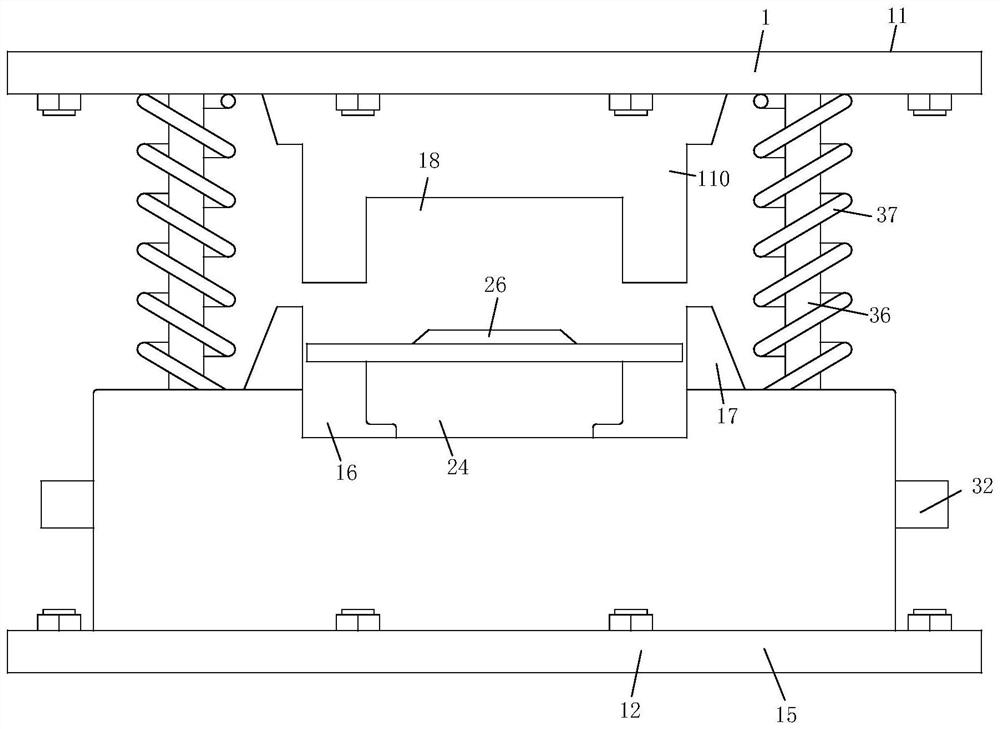
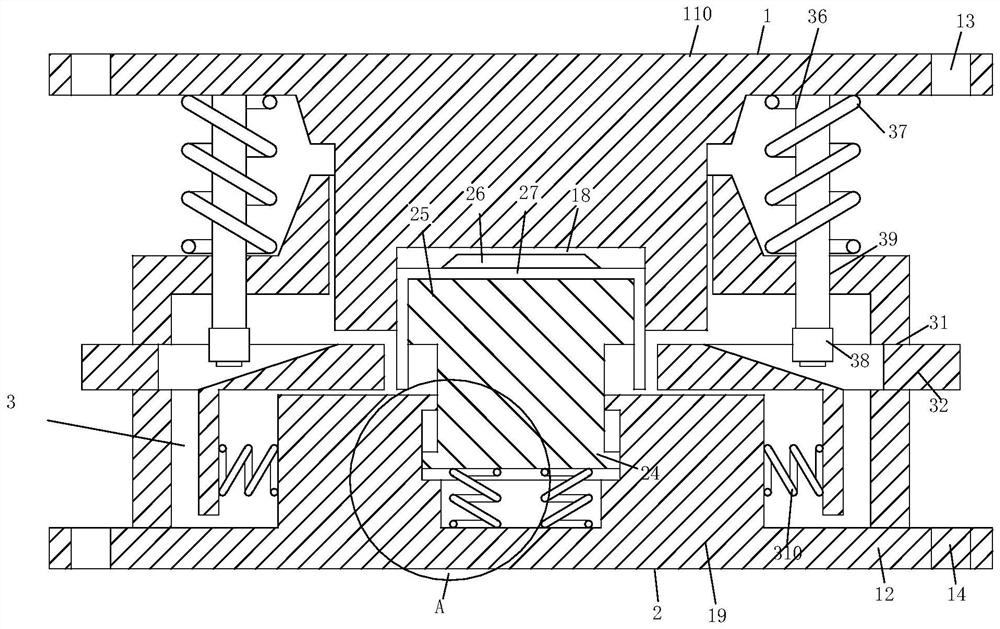
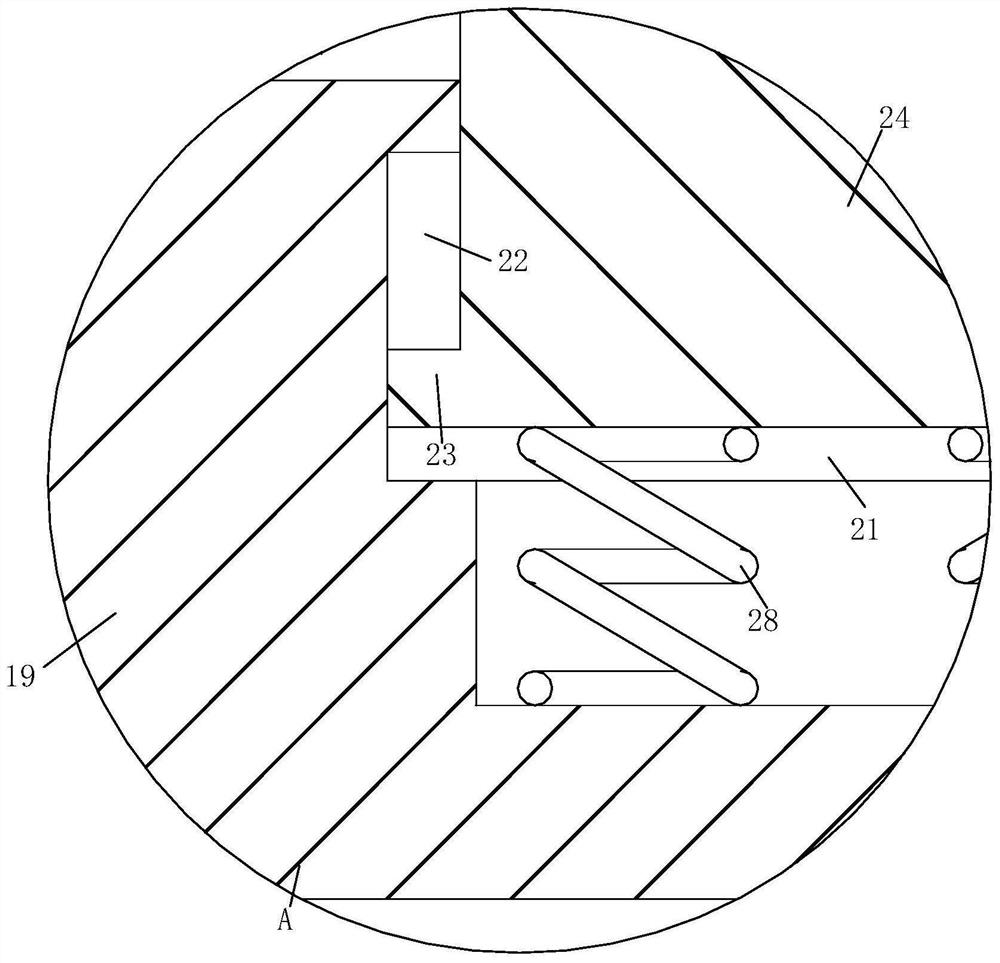
[0021] Such as Figure 1-Figure 5 As shown, a kind of hot stamping metal mold of the present invention includes a mold clamping mechanism 1, a demoulding mechanism 2 and a hemming mechanism 3, and the middle part of the mold clamping mechanism 1 is equipped with a demoulding mechanism 2, and the demoulding mechanism 2 Both sides of the mechanism 2 and in the clamping mechanism 1 are equipped with a folding mechanism 3. The setting of the demoulding mechanism 2 can facilitate the removal of the workpiece. The clamping mechanism 1 and the folding mechanism 3 can cooperate with each other, so that in a punching process, the The workpiece forms two 90-degree bending angles. The mold clamping mechanism 1 includes an upper template 11, a lower template ...


PUM


Abstract

The present invention relates to the technical field of hardware, specifically a hot stamping hardware mold, including a mold clamping mechanism, a demoulding mechanism and a hemming mechanism, a demoulding mechanism is installed in the middle of the mold clamping mechanism, and the demoulding mechanism Folding mechanisms are installed on both sides and in the mold clamping mechanism. The mold clamping mechanism includes an upper mold plate, a lower mold plate, an upper mold hole, a lower mold hole, a mold shell, a pick-up groove, a baffle plate, a mold groove, and a lower convex Platform and upper boss, the upper template is located above the lower template, and the four corners of the upper template are provided with upper die holes. The invention is a hot stamping metal mold, which has the characteristics of compact and reasonable structure and bidirectional stamping. At this time, the column head and the upper boss move down synchronously, the groove wall of the mold cavity can be bent for the first time along the side of the stamping part, and the column head can press the bent plate laterally along the groove wall to move the bent plate laterally Push the bottom end of the stamping part to bend, and then form a "C"-shaped channel steel wrapped on the outer wall of the mold table, which can be stamped and formed sequentially.

Description

technical field [0001] The invention relates to the technical field of hardware, in particular to a hot stamping metal mold. Background technique [0002] Hot stamping is a kind of part processing method. Firstly, the blank is heated to a certain temperature, and then it is stamped and quenched in the corresponding mold with a stamping machine to obtain the desired shape and realize the phase transformation of the metal material at the same time. Generally speaking, hot stamping forming technology is a technology that uses the principle of metal thermoplastic forming to improve the forming performance of materials, which greatly expands the application range of high-strength ultra-high-strength steel. [0003] In the process of hardware processing, hot stamping technology is widely used, which greatly improves the strength of hardware. As the basic material of large and small hardware, "C" section steel is widely used in the production of doors, windows, slide rails and hing...

Claims


Application Information

Patent Timeline
Patent Type & Authority Patents(China)
IPC IPC(8): B21D37/12B21D45/08B21D5/06
CPCB21D37/12B21D45/08B21D5/06
Inventor 陶安胡林斌
Owner 深圳市凯华五金制品有限公司
Learn More