Supercharge Your Innovation With Domain-Expert AI Agents!

Large 3D printer mechanism

A 3D printer, a large-scale technology, applied in the direction of additive processing, etc., can solve the problems of complex design structure, small printing area, and large occupied space, and achieve the effect of simple design structure, large printing area, and small occupied space

Pending Publication Date: 2020-06-16
青海交通职业技术学院
View PDF0 Cites 4 Cited by
  • Summary
  • Abstract
  • Description
  • Claims
  • Application Information

AI Technical Summary

Problems solved by technology

[0004] The purpose of the present invention is to solve the problem that the existing 3D printer mechanisms in the prior art are generally realized by frame or cross structures. Although these mechanisms can roughly meet the requirements of use, their design structures are complex, large in volume, and take up a lot of space. The printing area is small, resulting in the waste of resources, and a large-scale 3D printer mechanism is proposed

Method used


Image

  • Large 3D printer mechanism
  • Large 3D printer mechanism
  • Large 3D printer mechanism

Examples


Embodiment 1

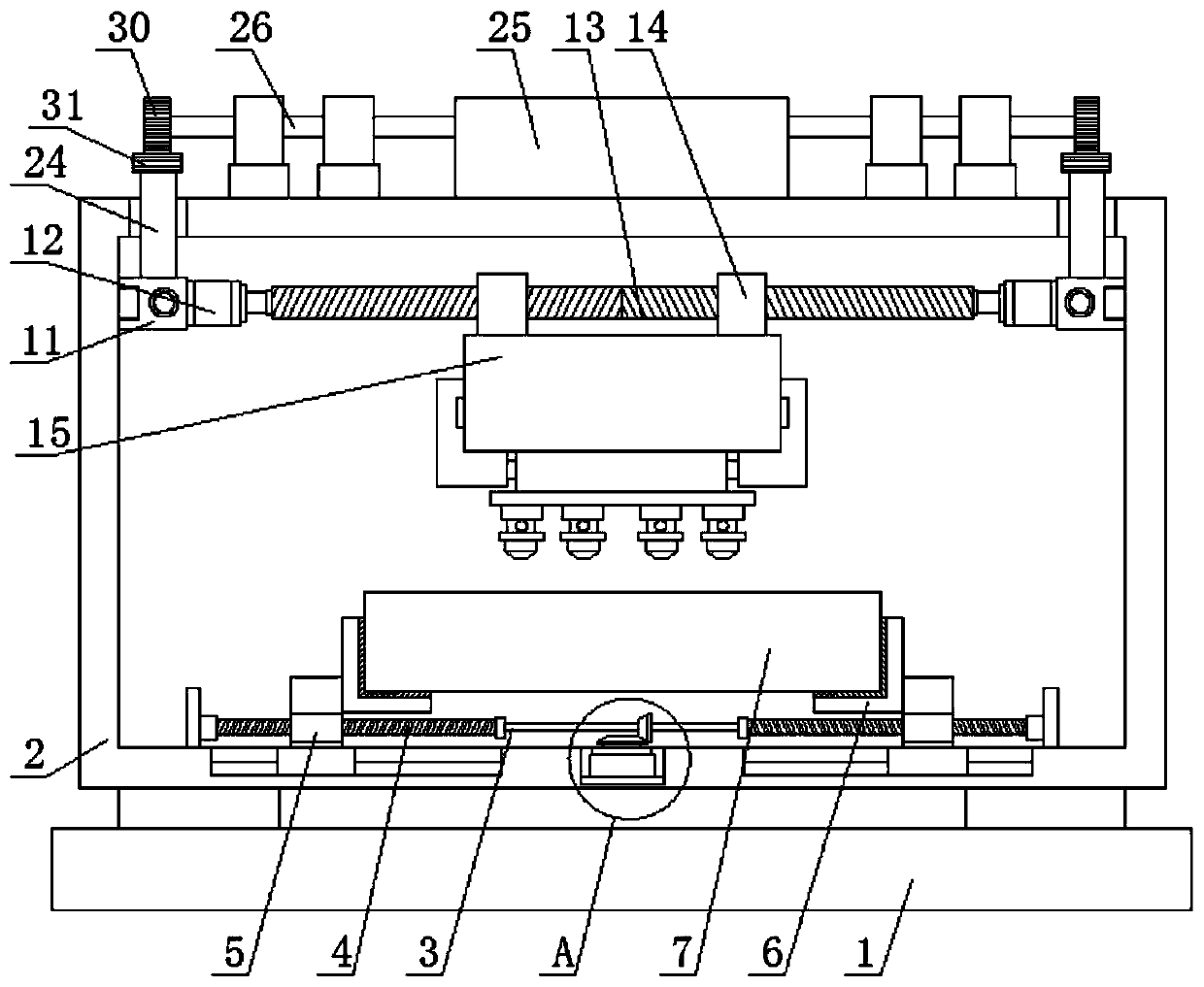
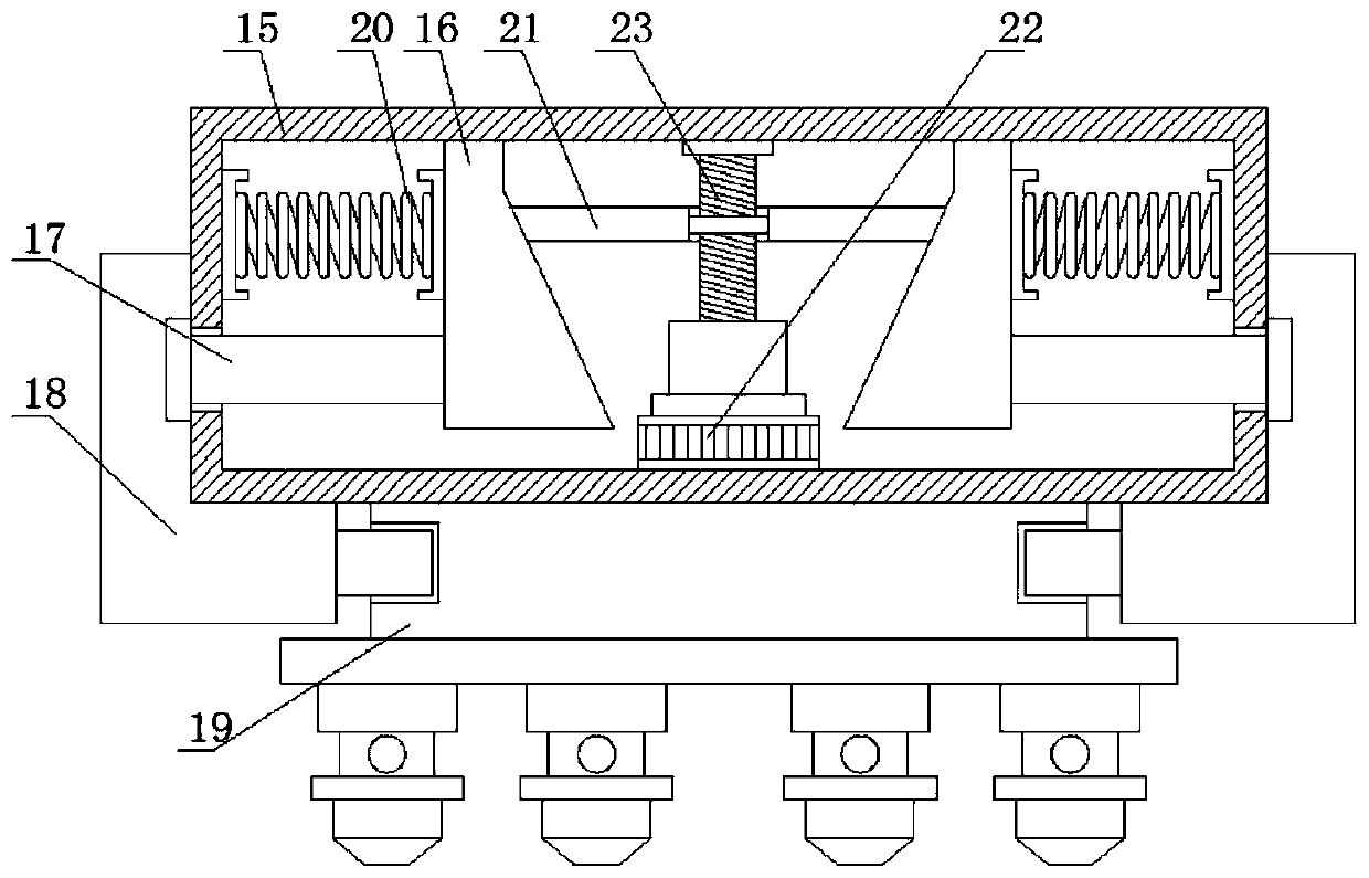
[0027] refer to Figure 1-5 , a large-scale 3D printer mechanism, including a base 1, a fixed frame 2 is fixedly installed on the top of the base 1, a clamping assembly is arranged on the fixed frame 2, and a workpiece 7 is clamped and fixed on the clamping assembly, and the fixed frame 2 A moving plate 11 is slidably connected to the inner walls on both sides, and a rotating motor 12 is fixedly installed on the side where the two moving plates 11 are close to each other, and the same screw rod 13 is fixedly installed on the output shafts of the two rotating motors 12, and the screw rod 13 is provided with two sections of thread that are arranged symmetrically, and two threaded blocks 14 that are arranged symmetrically are threaded on the screw mandrel 13, and the two sections of threads that are arranged symmetrically on the screw mandrel 13 run through the two threaded blocks 14 and connect with the threaded block respectively. 14 threaded connections, the bottom of the two ...

Embodiment 2

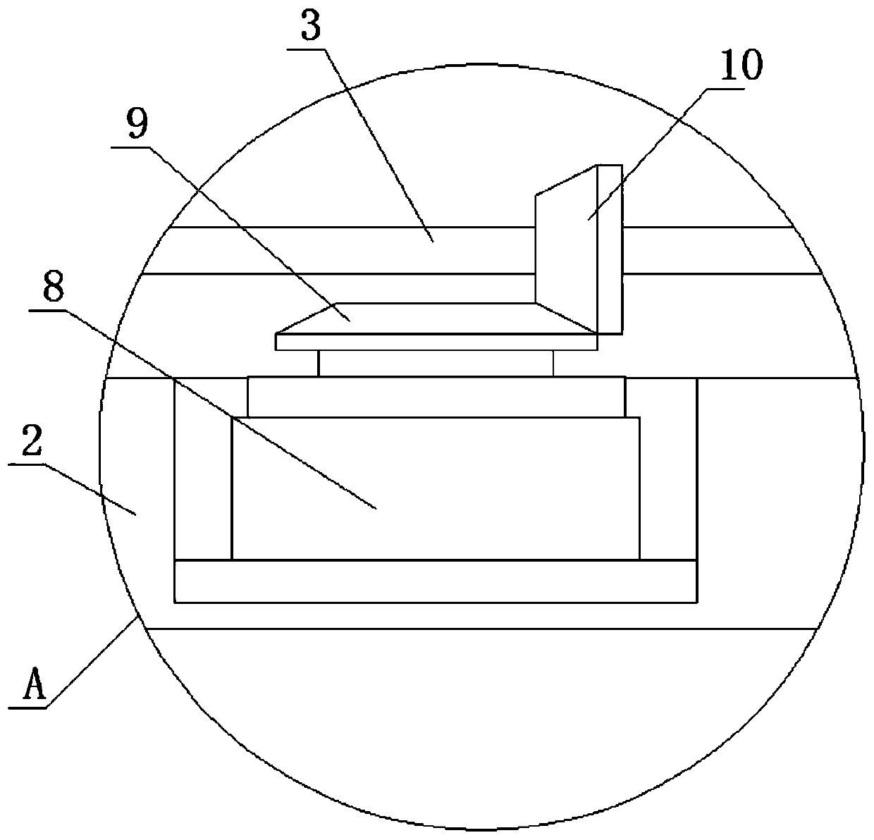
[0029]The clamping assembly includes a driving motor 8 fixedly installed on the fixed frame 2, a first bevel gear 9 is fixedly installed on the output shaft of the driving motor 8, two first screw rods 4 that are symmetrically arranged are rotated on the fixed frame 2, and The same rotating rod 3 is fixedly installed on the sides of the two first screw rods 4 close to each other, and the output shaft of the rotating rod 3 is fixedly installed with a second bevel gear 10, and the first bevel gear 9 and the second bevel gear 10 are meshed. Two sliding plates 5 arranged symmetrically are slidably connected on the fixed frame 2, and the two first screw rods 4 respectively pass through the two sliding plates 5 and are threadedly connected with the sliding plates 5, and the threads on the two first screw rods 4 are symmetrical. The sides of the two sliding plates 5 close to each other are fixedly equipped with L-shaped clamping plates 6, and the workpiece 7 is located between the two...


PUM


Abstract

The invention belongs to the field of 3D printers, and particularly relates to a large 3D printer mechanism. The problems that an existing 3D printer mechanism is achieved commonly through a frame type or cross structure, although the mechanism can roughly meet the use needs, the design structure is complex, the size is large, occupied space is large, the printing area is small, and resource wasteis caused can be solved. According to the following scheme, the large 3D printer mechanism comprises a base, a fixed frame is fixedly mounted on the top of the base, a clamping assembly is mounted onthe fixed frame, a machining part is clamped and fixed to the clamping assembly, moving plates are in sliding connection to the inner walls of the two sides of the fixed frame, the sides, close to each other, of the two moving plates are fixedly provided with rotating motors, and output shafts of the two rotating motors are fixedly provided with one same screw. Operation is easy, and a 3D printermechanism body is simple in design structure, small in size, small in occupied space, large in printing area, and capable of saving resources.

Description

technical field [0001] The invention relates to the technical field of 3D printers, in particular to a large-scale 3D printer mechanism. Background technique [0002] 3D printing is usually achieved using a digital technology material 3D printer. It is often used to make models in the fields of mold manufacturing and industrial design, and is gradually used in the direct manufacture of some products. There are already parts printed using this technology. The technology has applications in jewelry, footwear, industrial design, architecture, engineering and construction (AEC), automotive, aerospace, dental and medical industries, education, geographic information systems, civil engineering, firearms, and others. [0003] 3D printing (3DP) is a kind of rapid prototyping technology, also known as additive manufacturing [1]. 3D printers in the prior art are generally realized by frame or cross structures. Although these mechanisms can roughly meet the requirements of use, their...

Claims


Application Information

Patent Timeline
IPC IPC(8): B29C64/20B33Y30/00
CPCB29C64/20B33Y30/00
Inventor 王海春赵文天
Owner 青海交通职业技术学院
Features
  • R&D
  • Intellectual Property
  • Life Sciences
  • Materials
  • Tech Scout
  • Unparalleled Data Quality
  • Higher Quality Content
  • 60% Fewer Hallucinations
Learn More