Rail engineering vehicle transmission method

A technology for construction vehicles and rails, which is applied in the field of transmission control of dual-power source-driven rail construction vehicles to achieve the effects of reducing intermediate energy conversion points, reducing pipeline risk points, and high efficiency

Inactive Publication Date: 2020-06-16
ZHUZHOU TIMES ELECTRONICS TECH CO LTD +1
View PDF9 Cites 4 Cited by
  • Summary
  • Abstract
  • Description
  • Claims
  • Application Information

AI Technical Summary

Problems solved by technology

[0011] In view of this, the purpose of the present invention is to provide a transmission method for rail engineering vehicles to solve the technical problems of power transmission of dual power source rail operating vehicles in high-speed and low-speed travel modes, so as to meet the requirements for travel speed and control under different working conditions. Accuracy requirements

Method used


Image

  • Rail engineering vehicle transmission method
  • Rail engineering vehicle transmission method
  • Rail engineering vehicle transmission method

Examples


Embodiment 1

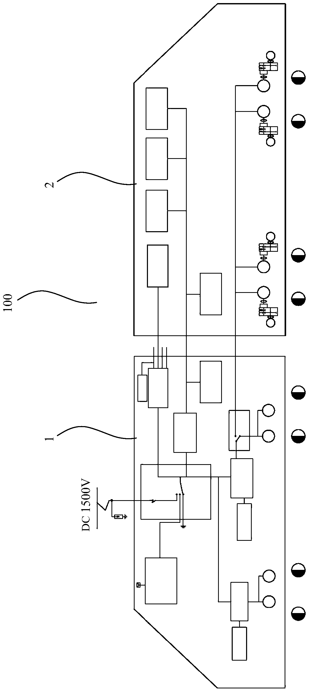
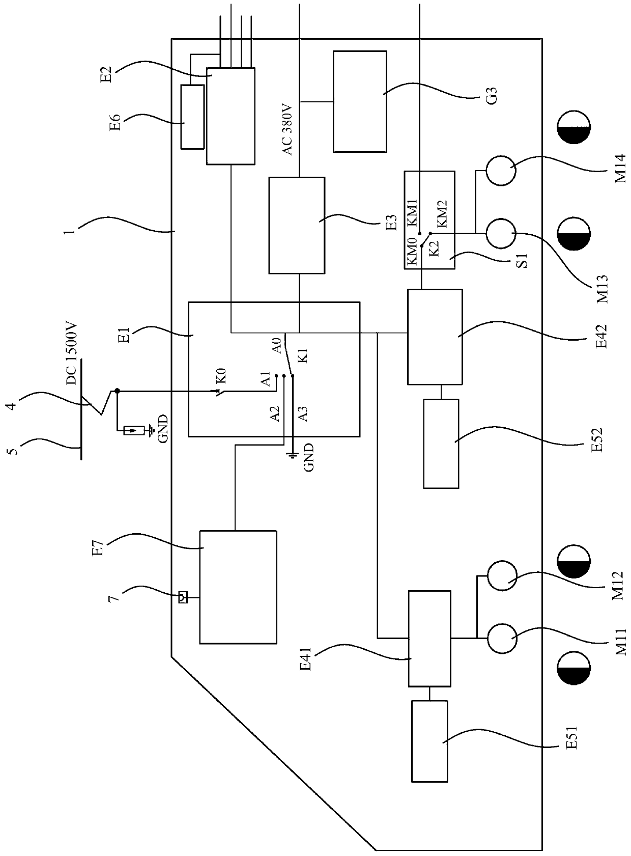
[0053] as attached figure 1 As shown, a kind of embodiment of the track engineering vehicle transmission system based on the method of the present invention, the track engineering vehicle 100 includes a power car 1 and a working vehicle 2, and the power car 1 is responsible for providing train power, high-speed running and low-speed running power source, and operating Car 2 is responsible for operating functions and realizing low and constant speed running. The transmission system of rail engineering vehicles specifically includes: the vehicle power supply system and high-speed running system arranged on the power car 1, the low-speed running system arranged on the working car 2, and the operating system partially or completely arranged on the working car 2. The vehicle power supply system provides power for the operating system, and can optionally provide power for the high-speed running system or the low-speed running system. The high-speed running system adopts electric dr...

Embodiment 2

[0072] An embodiment of the transmission method of a rail engineering vehicle of the present invention, the rail engineering vehicle 100 includes a power vehicle 1 and a working vehicle 2, and the power transmission method specifically includes the following steps:

[0073] A) Arrange the vehicle power supply system and high-speed running system on the power vehicle 1, and arrange the low-speed running system on the work vehicle 2; arrange it separately on the work vehicle 2, or arrange the operation system on the power vehicle 1 and the work vehicle 2;

[0074] B) The vehicle power supply system provides power for the operating system, and can optionally provide power for the high-speed running system or low-speed running system;

[0075] C) Realize high-speed running through the high-speed running system, which adopts electric drive traction to realize the running speed of rail engineering vehicles from 0 to 80km / h and the speed control accuracy of less than 0.5km / h;

[0076...

Embodiment 3

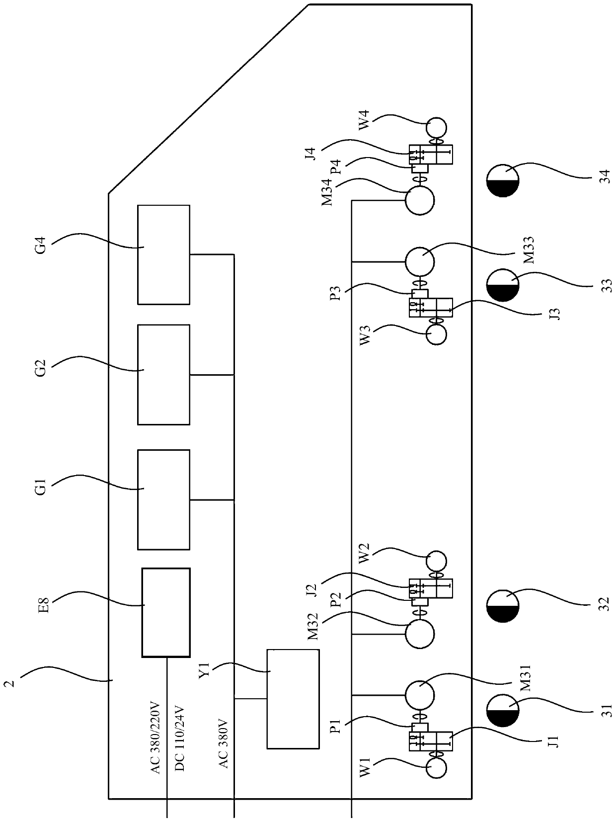
[0102] as attached Figure 4 to attach Figure 6 As shown, a rail milling car based on the transmission method of rail engineering vehicles described in Embodiment 2 is composed of a power car 1 and an operating vehicle 2. The power car 1 is responsible for providing train power, high-speed running and low-speed running power source, and the working vehicle 2 Responsible for operating functions and realizing low and constant speed travel. Wherein, the power car 1 includes an electrical room 11 , an inspection room 12 and a scrap bin 13 . Inside the electrical room 11 are arranged a traction battery cabinet (corresponding to the traction battery E7) 101, a low-voltage control cabinet 102, a high-voltage cabinet (corresponding to the high-voltage box E1) 107 and a converter control cabinet 108. In the maintenance room 12 there are a maintenance platform 103 , a tool cabinet 104 and a brake control cabinet 109 . The scrap iron bin 13 is provided with a working power supply box...


PUM


Abstract

The invention discloses a rail engineering vehicle transmission method, which comprises the following steps of: arranging a whole vehicle power supply system and a high-speed running system on a powervehicle, and arranging a low-speed running system on an operating vehicle; the operation vehicle is independently arranged, or an operation system is arranged on the power vehicle and the operation vehicle; b) the whole vehicle power supply system supplies power to the operation system, and selectively supplies power to the high-speed running system or the low-speed running system; c) high-speedwalking is realized through a high-speed walking system, and the high-speed walking system adopts electric transmission traction to realize high-speed walking and low control precision; and (D) low-speed walking is achieved through the low-speed walking system, all-electric transmission traction is adopted in the low-speed walking system, speed reduction is conducted through a speed reduction mechanism, and therefore low-constant-speed walking and high control precision are achieved. The technical problem of power transmission of the double-power-source rail operation vehicle in the high-speedwalking mode and the low-speed walking mode can be solved, and the requirements for the walking speed and the control precision under different working conditions are met.

Description

technical field [0001] The invention relates to the technical field of railway engineering machinery, in particular to a transmission control method for driving rail engineering vehicles with dual power sources (catenary power supply + traction battery power supply). Background technique [0002] As a widely used rail working vehicle, the rail milling and grinding vehicle is a rail engineering maintenance vehicle used to repair rail surface defects. The rail milling and grinding vehicle processes the surface of the rail through the milling unit and the grinding unit installed on the vehicle chassis, so that the parameters such as the roughness, wave grinding and profile of the rail surface reach the required value. The cutter on the milling unit mills the surface of the rail to eliminate damage and corrugation on the surface of the rail to control the cross-sectional profile. The grinding wheel on the grinding unit grinds the rail surface after milling chips to make the rai...

Claims


Application Information

Patent Timeline
Patent Type & Authority Applications(China)
IPC IPC(8): B60L3/00B60L9/04B60L50/60B61C3/02B61C9/38
CPCB60L3/00B60L9/04B60L50/60B61C3/02B61C9/38B60L2200/26Y02T10/70Y02T30/00
Inventor 雷张文肖樨刘勇汪海李永江刘莎方继武黄志松
Owner ZHUZHOU TIMES ELECTRONICS TECH CO LTD
Why Eureka
Try Eureka