A secondary structure anti-seepage and anti-leakage construction method

A secondary structure and construction method technology, applied in building structure, building maintenance, construction, etc., can solve the problems of the connection force drop of the old and new concrete interface, the joint gap, seepage, etc., so as to prevent leakage and improve the resistance The effect of compressive strength and good impermeability

Active Publication Date: 2021-12-14
广州芳建工程建设集团有限公司
View PDF0 Cites 0 Cited by
  • Summary
  • Abstract
  • Description
  • Claims
  • Application Information

AI Technical Summary

Problems solved by technology

[0004] The above-mentioned existing technical solutions have the following defects: However, since the secondary structure is constructed on the basis of the primary structure, the interface connection force between the old and new concrete drops more seriously, which makes the connection between the secondary structure and the primary structure easy to appear. gaps, resulting in percolation, therefore, there is still room for improvement

Method used


Image

  • A secondary structure anti-seepage and anti-leakage construction method
  • A secondary structure anti-seepage and anti-leakage construction method
  • A secondary structure anti-seepage and anti-leakage construction method

Examples


Embodiment 1

[0064] refer to figure 1 , is a secondary structure anti-seepage and anti-leakage construction method disclosed by the present invention, comprising the following specific steps:

[0065] S1. According to the requirements of the design drawings, mark the place where the primary structure needs to be constructed for the secondary structure, draw a line with chalk on the surface where the primary structure is about to be connected with the secondary structure, and circle the area where the primary structure is about to be connected with the secondary structure, forming Connection face ID.

[0066] S2. Gouging the surface of the structure at the area circled by the connection surface mark with a pick to form a connection groove, the length of the connection groove is consistent with the length of the area circled by the connection surface mark, and the width of the connection groove is the area circled by the connection surface mark 105% of the width, the depth of the connecting...

Embodiment 2-4

[0077] The difference with embodiment 1 is:

[0078] Each raw material addition (unit is Kg) is shown in Table 2 for details in the step S4:
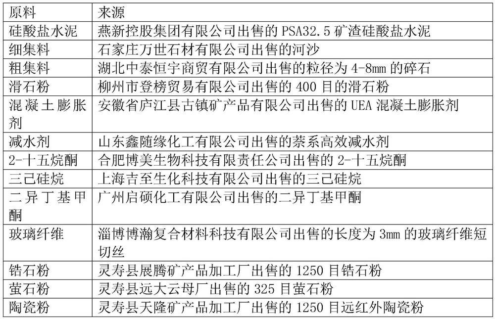
[0079] Table 2

[0080] raw material Example 2 Example 3 Example 4 Portland cement 100 100 100 water 100 110 100 Superplasticizer 10 9 10 talcum powder 35 40 38 concrete expansion agent 7 8 7.5 fine aggregate 325 350 333 coarse aggregate 175 200 166
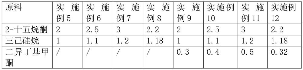
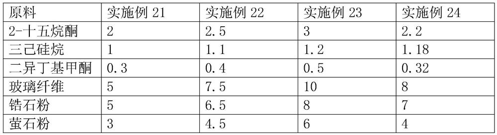
Embodiment 5-12

[0082] The difference with embodiment 4 is:

[0083] In step S42, one or more of 2-pentadecanone, trihexylsilane, and diisobutyl ketone is added, and the specific addition amount of each raw material (in Kg) is shown in Table 3

[0084] table 3

[0085]


PUM

PropertyMeasurementUnit
strengthaaaaaaaaaa

Abstract

The present invention relates to the technical field of secondary structure construction, in particular to a secondary structure anti-seepage and leak-proof construction method, which includes the following steps: S1. According to the design requirements, draw a line on the surface of the primary structure to circle the primary structure and the secondary structure. The area where the secondary structure is connected forms a connection surface mark; S2. Destroy the surface of the primary structure to form a concave connection groove, and the connection groove at least completely covers the area included in the connection surface mark; S3. Build the pouring formwork according to the secondary structure design drawing; S4 .Preparation of concrete grout; S5. Pouring concrete grout; S6. Curing with mold; S7. After the concrete grout solidifies, remove the pouring formwork to form a secondary structure; the concrete grout includes the following components in parts by mass: Portland cement 100 parts 300-350 parts of fine aggregate; 150-200 parts of coarse aggregate; 30-40 parts of talcum powder; 6-8 parts of concrete expansion agent; 90-110 parts of water. The invention has the effect that leakage is not easy to occur at the junction of the primary structure and the secondary structure.

Description

technical field [0001] The invention relates to the technical field of secondary structure construction, in particular to a secondary structure anti-seepage and anti-leakage construction method. Background technique [0002] At present, with the development of technology, concrete buildings are becoming more and more popular. Buildings made of reinforced concrete have higher stability and faster construction efficiency. The construction process of concrete buildings includes the primary structure (the load-bearing component part of the main structure) and the secondary Structures such as: filling walls, lintels, structural columns, parapets and other non-load-bearing structures. [0003] During the construction of the existing secondary structure, it is usually constructed on the frame of the primary structure by means of blocks or cast-in-place after the primary structure is solidified. The addition of the secondary structure can make the building more functional. , better...

Claims


Application Information

Patent Timeline
Patent Type & Authority Patents(China)
IPC IPC(8): E04G23/02C04B28/04
CPCE04G23/0266C04B28/04C04B2201/50C04B14/02C04B14/042C04B14/06C04B24/008C04B24/40C04B14/42C04B14/36C04B14/046C04B18/165C04B2103/0068C04B2103/302
Inventor 唐善伟彭程
Owner 广州芳建工程建设集团有限公司
Why Eureka
Try Eureka