
Coal mine mining industry drilling machine

A mining and mechanical technology, applied in drill pipes, drill pipes, drilling equipment, etc., can solve the problems of inconvenient use and inconvenient adjustment, and achieve the effect of convenient use.

Inactive Publication Date: 2020-06-16
崔广永
View PDF0 Cites 13 Cited by
  • Summary
  • Abstract
  • Description
  • Claims
  • Application Information

AI Technical Summary

Problems solved by technology

[0005] Aiming at the deficiencies in the prior art, one of the purposes of the present invention is to provide a coal mining drilling machine, which is mainly used to solve the problem that the existing drilling rig equipment for coal mine operations needs to frequently replace different lengths of drill pipes under different depth requirements, so that the use of Inconvenient, at the same time, the drilling rig equipment for coal mine operations is inconvenient to adjust according to the drilling angle

Method used


Image

  • Coal mine mining industry drilling machine
  • Coal mine mining industry drilling machine
  • Coal mine mining industry drilling machine

Examples


Embodiment 1

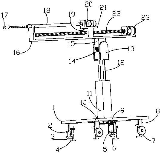
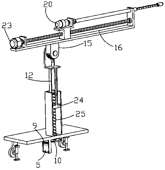
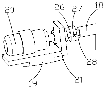
[0030] Such as Figure 1-5 A kind of coal mine mining drilling machinery shown, comprises bottom plate 1, first driving motor 6, second driving motor 20 and third driving motor 23, first driving motor 6, second driving motor 20 and third driving motor 23 are selected Servo motor, bottom plate 1 is fixedly connected with outrigger 8, outrigger 8 is rotatably connected with roller 7, outrigger 8 is connected with fixed structure, fixed structure includes horizontal plate 2, electric push rod 3 and rubber plate 4, horizontal plate 2 and support The legs 8 are fixedly connected, and the through hole of the horizontal plate 2 is fixedly connected with the electric push rod 3, and the telescopic end of the electric push rod 3 is fixedly connected with the rubber plate 4, and the electric push rod 3 of the fixed structure drives the rubber plate 4 to move downward. The rubber plate 4 is in contact with the ground to fix the position of the drilling rig equipment used in coal mine ope...

Embodiment 2

[0032] Such as Figure 1-5 The coal mining drilling machine shown includes a bottom plate 1, a first drive motor 6, a second drive motor 20 and a third drive motor 23. The bottom plate 1 is fixedly connected with a leg 8, and the leg 8 is rotatably connected with a roller 7. The outrigger 8 is connected with a fixed structure, the bottom plate 1 is rotatably connected with a first threaded rod 25 through a fixedly connected bearing, the bottom of the first threaded rod 25 is fixedly connected with a driven ring gear 10, the bottom plate 1 is fixedly connected with a mounting frame 5, and the mounting frame 5 is fixedly connected with the first driving motor 6, the output end of the first driving motor 6 is fixedly connected with the driving ring gear 9, the driving ring gear 9 is engaged with the driven ring gear 10, and the top of the base plate 1 is fixedly connected with a square sleeve plate 11, The square cover plate 11 is fitted and slidably connected with a square slide...

Embodiment 3

[0034] Such as Figure 1-5 The coal mining drilling machine shown includes a bottom plate 1, a first drive motor 6, a second drive motor 20 and a third drive motor 23. The bottom plate 1 is fixedly connected with a leg 8, and the leg 8 is rotatably connected with a roller 7. The outrigger 8 is connected with a fixed structure, the bottom plate 1 is rotatably connected with a first threaded rod 25 through a fixedly connected bearing, the bottom of the first threaded rod 25 is fixedly connected with a driven ring gear 10, the bottom plate 1 is fixedly connected with a mounting frame 5, and the mounting frame 5 is fixedly connected with the first driving motor 6, the output end of the first driving motor 6 is fixedly connected with the driving ring gear 9, the driving ring gear 9 is engaged with the driven ring gear 10, and the top of the base plate 1 is fixedly connected with a square sleeve plate 11, The square cover plate 11 is fitted and slidably connected with a square slide...


PUM


Abstract

The invention relates to a coal mine mining industry drilling machine, and belongs to the technical field of coal mine machine installation. The coal mine mining industry drilling machine comprises abottom plate, supporting legs are arranged on the bottom plate, rollers are arranged on the supporting legs, fixed structures are arranged on the supporting legs, a first threaded rod is arranged , onthe bottom plate, the first threaded rod is provided with a driven gear ring, a first driving motor is provided with a driving gear ring, the driving gear ring is provided with the driven gear ring,the bottom plate is provided with a square sleeve plate, the square sleeve plate is provided with a square sliding block, the square sliding block is connected with the first threaded rod, the squaresliding block is provided with a supporting rod, the supporting rod is provided with an angle adjustment structure, the angle adjustment structure is provided with an inverted F-shaped frame, the inverted F-shaped frame is provided with a third driving motor, the third driving motor is provided with a second threaded rod, the second threaded rod is provided with a movable block, and the movable block is provided with an L-shaped plate; and the L-shaped plate is provided with a second driving motor, the second driving motor is provided with a mounting sleeve, a first square inserted block is arranged in the mounting sleeve, the first square inserted block is provided with a length adjustment structure, and a drill bit is arranged at the left end of the length adjustment structure. Accordingto drilling rig equipment for coal mine operation, adjustment can be conveniently carried out according to the drilling angle.

Description

technical field [0001] The invention relates to the technical field of setting up coal mine machinery, in particular to a coal mine drilling machine. Background technique [0002] Coal mines are areas where human beings exploit coal resources in coal-rich mining areas. They are generally divided into underground coal mines and open-pit coal mines. When the distance to the surface is very close, it is generally chosen to directly strip the surface soil layer to dig coal. This is an open-pit coal mine. Most of the coal mines in my country are underground coal mines. my country's economic construction has achieved rapid development in recent years, and economic development is inseparable from nature. For the mining and utilization of energy, my country's coal resources are particularly rich, so the rational exploitation and utilization of coal resources plays a vital role in my country's economic development. [0003] Drilling rig is one of the necessary drilling equipment widel...

Claims


Application Information

Patent Timeline
Patent Type & Authority Applications(China)
IPC IPC(8): E21B7/02E21B15/00E21B17/03
CPCE21B7/024E21B15/003E21B17/03
Inventor 崔广永沈建廷
Owner 崔广永
Learn More