Molten salt electrode boiler heat storage and power generation system

A technology of a power generation system and an electrode boiler, which is applied in the field of energy storage, can solve the problems of limited promotion and application, high cost, and no engineering promotion and application value, and achieves the effects of flexible operation mode, large heating power, and meeting heating requirements.

Inactive Publication Date: 2020-06-16
DONGFANG BOILER GROUP OF DONGFANG ELECTRIC CORP
View PDF3 Cites 8 Cited by
  • Summary
  • Abstract
  • Description
  • Claims
  • Application Information

AI Technical Summary

Problems solved by technology

The cost of pumped storage is relatively low, and the technology is very mature, but the construction site is restricted by water resources and geographical conditions, and its promotion and application are limited
Compressed air energy storage also needs resource conditions such as caverns to have application value, otherwise the energy storage method of air storage tank is expensive and has no engineering promotion and application value

Method used


Image

  • Molten salt electrode boiler heat storage and power generation system
  • Molten salt electrode boiler heat storage and power generation system

Examples


Embodiment 1

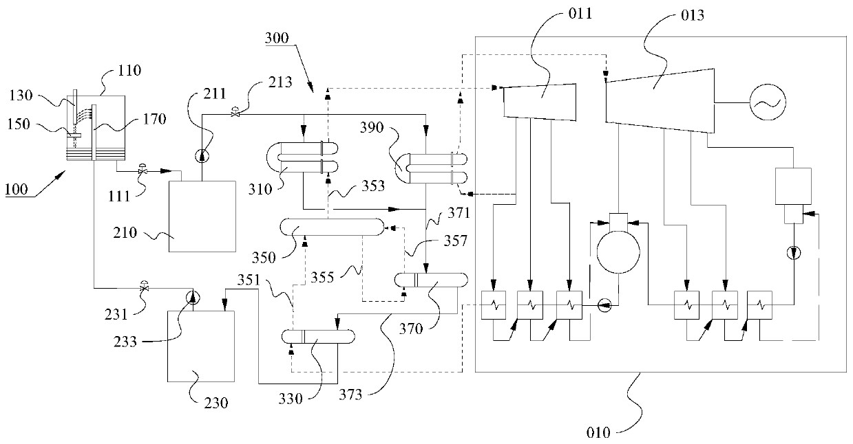
[0043] This embodiment provides a molten salt electrode boiler heat storage power generation system, please refer to figure 1 , this molten salt electrode boiler heat storage power generation system includes a heating part 100, a high temperature molten salt storage tank 210 and a heat utilization part 300;

[0044] The heating part 100 includes a furnace body 110, and a low-temperature molten salt supply head formed by a high-voltage electrode 130, a neutral electrode 150 and a molten salt distribution nozzle 170 arranged in the furnace body 110;

[0045] The high-voltage electrode 130 is used to connect to the power generation system, and the low-temperature molten salt supply head is used to fill the furnace body 110 with low-temperature molten salt;

[0046] One end of the high-temperature molten salt storage tank 210 is connected to the bottom of the furnace body 110, and the other end is connected to the heat utilization unit 300; The outlet regulating valve of the furn...

Embodiment 2

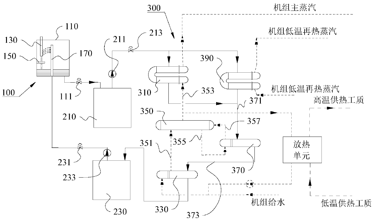
[0071] This embodiment provides a molten salt electrode boiler heat storage power generation system, please refer to figure 2The difference between this molten salt electrode boiler heat storage power generation system and the molten salt electrode boiler heat storage power generation system provided in Embodiment 1 is that when the heat storage unit provides power and external heat is required, the steam drum 350 is provided with a The seventh pipe 359 from which the saturated steam is drawn leads the saturated steam into the exothermic unit 320 , and in the exothermic unit 320 the temperature of the fluid used for industrial steam supply or heating is raised. After the saturated steam cools down and mixes with the unit feed water, it returns to the preheater 330 for the next cycle. When only heating is required and the heat storage unit is not required to generate electricity, the molten salt can be bypassed through the superheater 310 and the reheater 390, and the molten s...


PUM


Abstract

The invention provides a molten salt electrode boiler heat storage and power generation system, and belongs to the field of energy storage. The system involves a heating part, a high-temperature molten salt storage tank and a heat utilization part; the heating part comprises a boiler body, a high-voltage electrode, a neutral electrode and a low-temperature molten salt supply head, wherein the high-voltage electrode, the neutral electrode and the low-temperature molten salt supply head are arranged in the boiler body, the high-voltage electrode is used for being connected with a power generation system, and the low-temperature molten salt supply head is used for filling the boiler body with low-temperature molten salt; one end of the high-temperature molten salt storage tank is connected with the bottom of the boiler body, and the other end of the high-temperature molten salt storage tank is connected with the heat utilization part; and the heat utilization part is used for carrying outheat exchange on the molten salt sent out by the high-temperature molten salt storage tank and a water working medium for pushing the steam turbine to act, and sending the cooled molten salt back tothe boiler body. Wind power photovoltaic curtailed electricity is used for heating the molten salt and storing heat in the off-peak period of electricity utilization, and high-temperature molten saltis used for heating feed water to generate high-temperature and high-pressure steam in the peak period of electricity utilization, so that the steam turbine is pushed to act, he stored heat is converted into electric energy to be output, and the curtailed wind and light can be effectively consumed to realize large-scale storage and scheduling of non-water renewable energy power.

Description

technical field [0001] The invention relates to the field of energy storage, in particular to a heat storage and power generation system for a molten salt electrode boiler. Background technique [0002] As the installed power of unstable power sources such as wind power and photovoltaics in my country is increasing, and the installed capacity of coal-fired generators is limited, the output of unstable and discontinuous power sources in the entire power grid has increased year by year. It will pose a great threat to the safe operation of the power grid; second, when the load on the power consumption side increases, the power on the power generation side cannot keep up, resulting in insufficient power supply capacity. The current countermeasures are to use coal-fired power plants for peak regulation or to add a large number of wind power and photovoltaic installations. However, when the installed capacity of wind power and photovoltaics exceeds the regulation capacity of the g...

Claims


Application Information

Patent Timeline
Patent Type & Authority Applications(China)
IPC IPC(8): F22B1/30F28D20/00F01D15/10
CPCF01D15/10F22B1/30F28D20/0034F28D2020/0047Y02E60/14Y02E70/30
Inventor 李有霞奚正稳孙登科
Owner DONGFANG BOILER GROUP OF DONGFANG ELECTRIC CORP
Why Eureka
Try Eureka