Heat exchanger

A technology of heat exchangers and heat exchange tubes, applied in heat exchange equipment, heat exchanger sealing devices, heat exchangers, etc., can solve the problems of rigid joint leakage, increase maintenance frequency and cost, etc.

Pending Publication Date: 2020-06-16
智能热有限公司
View PDF13 Cites 2 Cited by
  • Summary
  • Abstract
  • Description
  • Claims
  • Application Information

AI Technical Summary

Problems solved by technology

Ultimately, every welded joint or other type of rigid joint runs the risk of leaking, which again increases the frequency and cost of required maintenance

Method used


Image

  • Heat exchanger
  • Heat exchanger
  • Heat exchanger

Examples


Embodiment Construction

[0083] Specific advantages of the invention

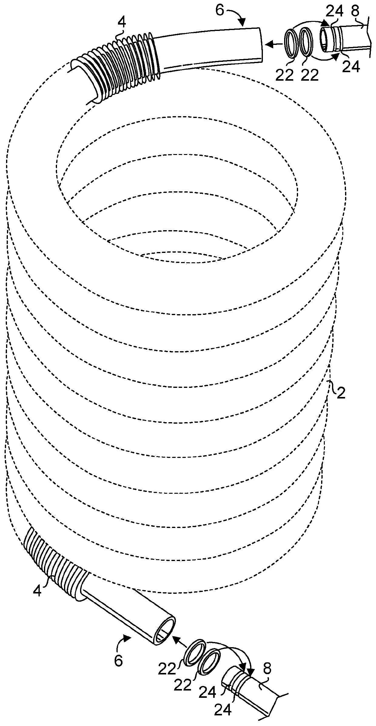
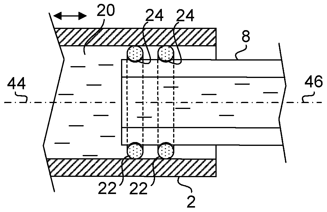
[0084] The present heat exchanger does not utilize conventional welded joints for fluid conductors, thereby eliminating the possibility of stress corrosion cracking associated with conventional welded joints. Every conventional welded joint is at risk of corrosion and leakage.

[0085] Since the present heat exchanger allows expansion and contraction of the heat exchange tubes, it is robust against thermal cycling.

[0086] The present heat exchanger includes a low mass of heat exchange tubes which allows for quick response to changing flow rates within the heat exchange tubes.

[0087] The present heat exchanger includes large channels, which allow high flow rates and minimize pressure drop and calcium carbonate fouling.

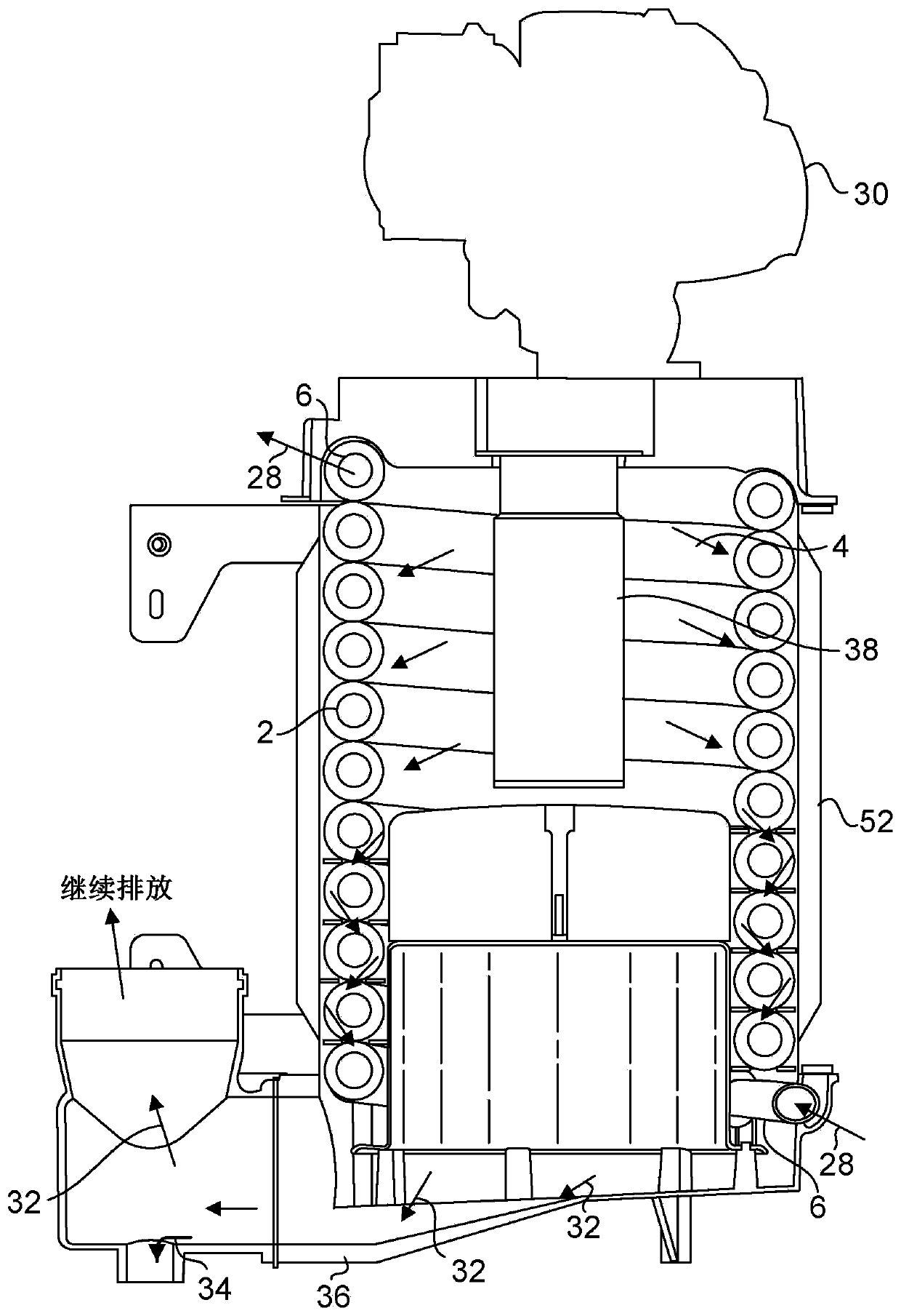
[0088] The present heat exchanger comprises: heat exchange tubes provided with a vertically disposed lumen; and a blower causing a flue flow that pushes condensate down and away from the heat exchange tubes to...


PUM


Abstract

A heat exchanger comprises (a) a fluid conductor including a heat exchange tubing including a first end and a lumen; and (b) a first connecting tubing including an outer surface, a lumen and a first sealing ring disposed about the outer surface of the first connecting tubing, wherein the first connecting tubing is configured for insertion into the lumen of the heat exchange tubing at the first endsuch that the first sealing ring comes in sealing engagement with the first connecting tubing and the heat exchange tubing while allowing relative movement between the heat exchange tubing and the first connecting tubing and a fluid flow is confined within a lumen formed of the lumen of the first connecting tubing and the lumen of the heat exchange tubing.

Description

[0001] Priority claims and related applications [0002] Continuation-in-Part Application Claiming the Benefit of Priority to U.S. Nonprovisional Application No. 15 / 903,544, filed February 23, 2018, which in turn claims Serial No. 62 / 463,584, filed February 24, 2017 The benefit of priority of the U.S. provisional application. The entire contents of each of these aforementioned applications are hereby incorporated by reference. technical field [0003] The present invention relates to a heat exchanger. More specifically, the invention is directed to a heat exchanger having a weld-free connection of heat exchange tubes to their connecting tubes on each end of the heat exchange tubes. Background technique [0004] In a tankless fluid heating system, it is important to have a responsive heat exchanger since the fluid supplied to its end user is not heated in advance and stored in anticipation of future demand. In a fluid heater that functions by transferring heat from a heate...

Claims


Application Information

Patent Timeline
Patent Type & Authority Applications(China)
IPC IPC(8): F24H9/18F28D7/04F28F21/08F28F19/00F28F11/00F28F1/24
CPCF24H9/1809F28D7/04F28F21/083F28F19/00F28F11/00F28F1/24F28D2021/0024F28D7/024F28D21/0007F28F9/0246F28F9/26F28F2230/00F24H1/165F24H1/43F16L21/035F16L21/022F16L21/03F16L51/00F16L27/125F28F2265/26F28F9/0236
Inventor 斯里达尔·德瓦斯加马尼斯瓦普瑞萨德·阿卡萨姆
Owner 智能热有限公司
Why Eureka
Try Eureka