High-energy X-ray CT device based on phase contrast imaging and imaging method

A phase contrast imaging and imaging device technology, applied in the field of CT detection, can solve the problems of low image resolution, poor spatial resolution, and unsatisfactory CT image quality.

Pending Publication Date: 2020-06-16
INST OF FLUID PHYSICS CHINA ACAD OF ENG PHYSICS
View PDF9 Cites 0 Cited by
  • Summary
  • Abstract
  • Description
  • Claims
  • Application Information

AI Technical Summary

Problems solved by technology

[0006] The purpose of the present invention is to provide a high-energy X-ray CT device and imaging method based on phase contrast imaging, to solve the problem that the existing high-energy X-ray absorption contrast (transmission) CT technology leads to the unsatisfactory quality of the acquired CT imag

Method used


Image

  • High-energy X-ray CT device based on phase contrast imaging and imaging method
  • High-energy X-ray CT device based on phase contrast imaging and imaging method
  • High-energy X-ray CT device based on phase contrast imaging and imaging method

Examples


Embodiment 1

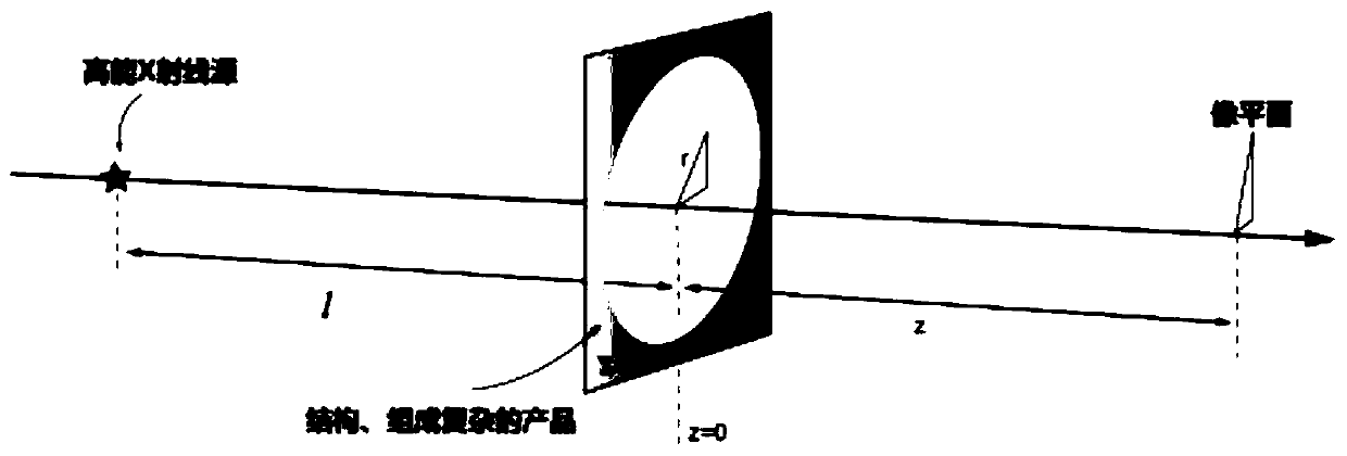
[0043] like Figure 1-Figure 2 As shown, a high-energy X-ray CT device based on phase contrast imaging includes a high-energy X-ray source, a sample stage and an imaging device;

[0044] The high-energy X-ray source is a quasi-single-energy gamma-ray source, which is an irradiation light source for the sample, and directional emits and irradiates and transmits the sample;

[0045] The sample stage is used to place the sample. After the high-energy X-ray source passes through the sample, the transmitted X-ray is transmitted in a wave manner and coherently superimposed at the image plane behind the sample to form photon intensity information containing phase and amplitude information;

[0046] The imaging device is arranged at the image plane behind the sample, and is used to receive X-rays passing through the sample and coherently superimpose at the image plane to form photon intensity information containing phase and amplitude information, and convert the photon intensity info...

Embodiment 2

[0053] This embodiment is based on embodiment 1, and the difference with embodiment 1 is:

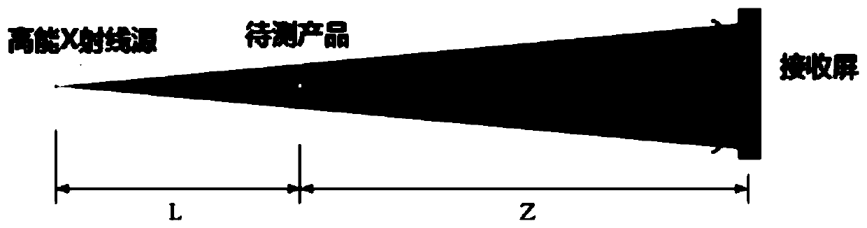
[0054] In this embodiment, the X-ray energy (X-ray wavelength λ) of the high-energy X-ray source is 4MeV, and the X-ray source spot size σ s is 5 microns, the pixel size of the camera system detector d pixel If it is 100 microns, the source-object-image relationship is: 0-150m-300m, which can effectively resolve the 50-micron defects in a tungsten block with a thickness of 70mm.

[0055] An imaging method of a high-energy X-ray CT device based on the above-mentioned phase-contrast imaging, comprising the following steps:

[0056] 1) The high-energy X-ray source reaches the sample to form a coherent X-ray source, then the X-ray source irradiates and penetrates the sample, and the transmitted X-rays are transmitted in a wave manner and coherently superimposed at the image plane behind the sample to form Photon intensity information containing phase and amplitude information, the imaging...


PUM


Abstract

The invention discloses a high-energy X-ray CT device based on phase contrast imaging and an imaging method. The high-energy X-ray CT device comprises a high-energy X-ray source, a sample table and animaging device, wherein the high-energy X-ray source is a high-energy X-ray punctuality light source, is an irradiation light source of a sample and is used for directionally emitting and irradiatingand transmitting the sample; the sample table is used for placing a sample, and after the high-energy X-ray source penetrates through the sample, transmitted X-rays are transmitted in a fluctuation mode and are coherently superposed on an image plane behind the sample to form photon intensity information containing phase and amplitude information; and the imaging device is arranged on an image plane behind the sample and is used for converting photon intensity information into an image signal. According to the method, the problems that the quality of the obtained CT image is not ideal and thespatial resolution is poor due to the existing CT technology based on high-energy X-ray absorption contrast, particularly, the resolution of the obtained image of the micro gap in the product is verylow, the micro gap is visible and unmeasurable, and the micro defects are difficult to distinguish are solved.

Description

technical field [0001] The invention relates to the technical field of CT detection, in particular to a phase-contrast imaging-based high-energy X-ray CT device and an imaging method. Background technique [0002] Precious products composed of high-density material parts, such as equipment, devices, components and parts, etc., have the characteristics of complex internal structure, high design and installation precision, non-detachable and long expected life cycle due to design requirements. Before delivery and during the service life cycle, the internal structure status monitoring is carried out according to the plan, so as to grasp its important parameters and parameter changes, and provide accurate evaluation basis for product quality, performance and life evaluation. [0003] X-rays can penetrate visible light-opaque products, and the intensity of X-rays that pass through the product carries information about the internal status of the product. Using specific informatio...

Claims


Application Information

Patent Timeline
IPC IPC(8): G01N23/046G01N23/041
CPCG01N23/046G01N23/041G01N2223/03G01N2223/1016G01N2223/401G01N2223/646G01N2223/645
Inventor 章林文刘进夏连胜张篁阳庆国李晶
Owner INST OF FLUID PHYSICS CHINA ACAD OF ENG PHYSICS
Why Eureka
Try Eureka