
Rotary transformer

A rotary transformer and rotor technology, applied in the field of transformers, can solve the problems of poor consistency of batch products, low production efficiency, complicated winding, etc., and achieve the effect of convenient processing, simple structure and firm connection

Inactive Publication Date: 2020-06-16
GUANGDONG WELLING AUTO PARTS CO LTD
View PDF11 Cites 3 Cited by
  • Summary
  • Abstract
  • Description
  • Claims
  • Application Information

AI Technical Summary

Problems solved by technology

In the prior art, the stator of the salient pole resolver has three sets of windings distributed per tooth, the winding is complex, the production efficiency is low, and the consistency of batch products is poor
[0003] In the related art, the stator and rotor of the resolver are divided into two parts along the axial direction, which provides a solution to simplify the winding process and realize automatic production, but the axial length of this solution is doubled compared with the traditional solution. The application is still limited in the occasions where the system installation space is sensitive

Method used


Image

  • Rotary transformer
  • Rotary transformer
  • Rotary transformer

Examples


Embodiment Construction

[0045] In order to understand the above-mentioned purpose, features and advantages of the present invention more clearly, the present invention will be further described in detail below in conjunction with the accompanying drawings and specific embodiments. It should be noted that, in the case of no conflict, the embodiments of the present application and the features in the embodiments can be combined with each other.

[0046] In the following description, many specific details are set forth in order to fully understand the present invention. However, the present invention can also be implemented in other ways different from those described here. Therefore, the protection scope of the present invention is not limited by the specific details disclosed below. EXAMPLE LIMITATIONS.

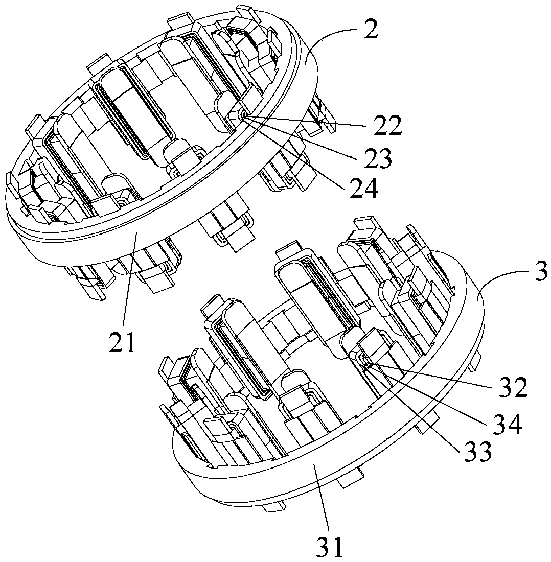
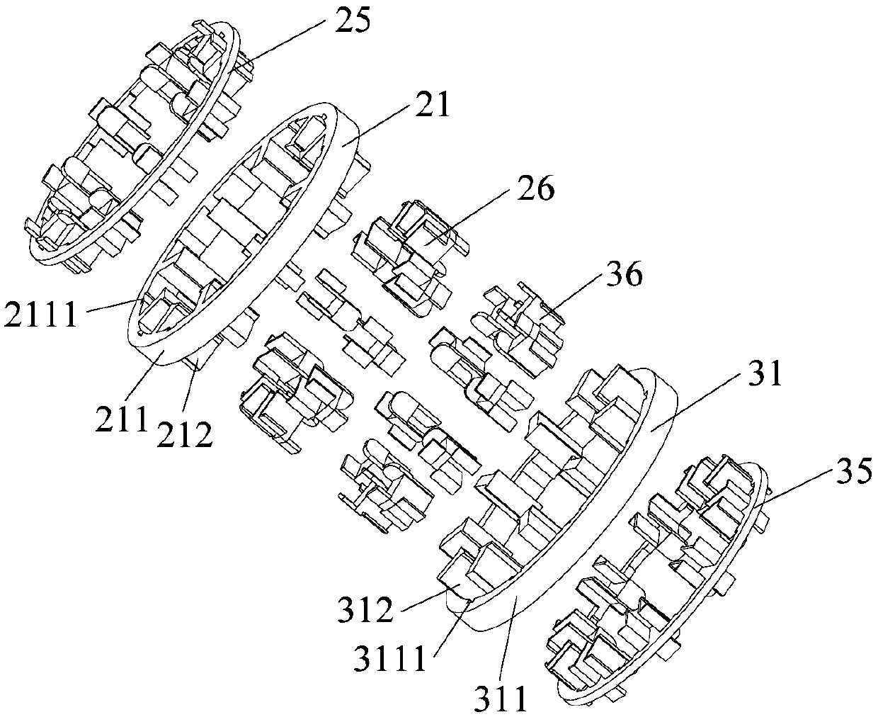
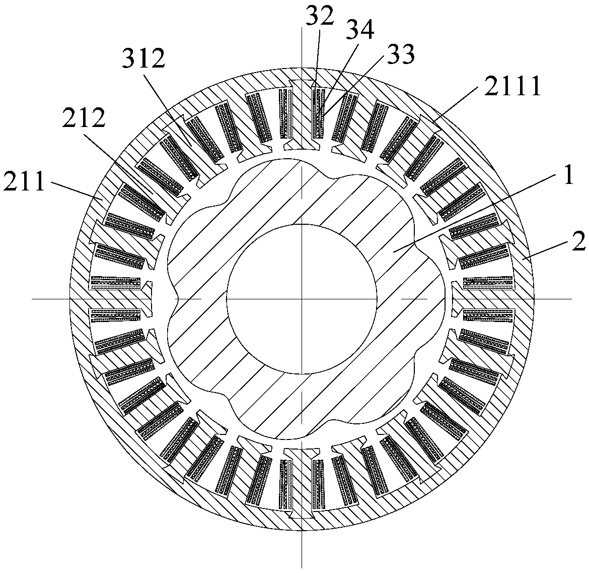
[0047] Refer below Figure 1 to Figure 8 A resolver according to some embodiments of the present invention is described.

[0048] Such as Figure 1 to Figure 3 As shown, a rotary transformer provi...


PUM


Abstract

The invention provides a rotary transformer. The rotary transformer comprises a rotor and a stator; the appearance of a rotor iron core comprises X concave-convex parts which form X pairs of pole pairs of the rotary transformer; the stator comprises a first stator split body and a second stator split body; the first stator split body and the second stator split body are in butt joint in an axial direction in a matched mode to form S stator grooves and corresponding S stator teeth; a first exciting winding, a first sine winding and a first cosine winding are sequentially wound on the first stator teeth of the first stator split body; and a second exciting winding, a second cosine winding and a second sine winding are sequentially wound on the second stator teeth of the second stator split body. According to the rotary transformer provided by the invention, a winding space in a winding process can be increased; automatic production is facilitated; production efficiency is improved; and the position detection precision of the rotary transformer is improved.

Description

technical field [0001] The present invention relates to the technical field of transformers, in particular to a rotary transformer, in particular to a salient pole rotary transformer. Background technique [0002] Salient pole resolvers are widely used in occasions that require high safety performance due to their simple fabrication, high stability, and good temperature resistance, such as automotive electric power steering (EPS) motors, traction motors, and starter generator (ISG) motors. In the prior art, the stator of the salient pole resolver has three sets of windings distributed on each tooth, the winding is complicated, the production efficiency is low, and the consistency of batch products is poor. [0003] In the related art, the stator and rotor of the resolver are divided into two parts along the axial direction, which provides a solution to simplify the winding process and realize automatic production, but the axial length of this solution is doubled compared wit...

Claims


Application Information

Patent Timeline
Patent Type & Authority Applications(China)
IPC IPC(8): H01F38/18H02K1/22H02K1/16H02K3/48H02K3/50
CPCH01F38/18H02K1/16H02K1/22H02K3/48H02K3/50
Inventor 万佳葛笑
Owner GUANGDONG WELLING AUTO PARTS CO LTD
Learn More