Stator tooth, stator and motor

A stator tooth and stator technology, applied in the direction of electrical components, electromechanical devices, electric components, etc., can solve the problems of low motor manufacturing efficiency, achieve the effects of reducing material costs, simple manufacturing, and improving manufacturing efficiency

Pending Publication Date: 2020-06-16
WELLING WUHU MOTOR MFG +1
View PDF5 Cites 2 Cited by
  • Summary
  • Abstract
  • Description
  • Claims
  • Application Information

AI Technical Summary

Problems solved by technology

[0002] At present, in the traditional motor with concentrated winding, there are ends of the winding, which will increase the material cost of the motor, and the traditional motor needs to wind the winding separately on each stator tooth, resulting in low efficiency of motor manufacturing

Method used


Image

  • Stator tooth, stator and motor
  • Stator tooth, stator and motor
  • Stator tooth, stator and motor

Examples


Embodiment 1

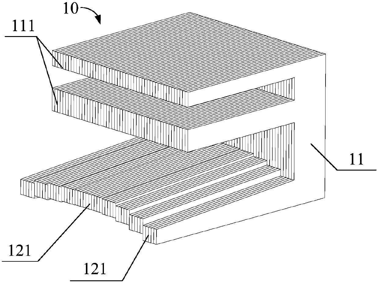
[0067] The winding portion 12 includes a plurality of stepped portions 121 arranged along the circumferential direction of the stator, such as figure 1 and figure 2 As shown, a plurality of stepped parts 121 are connected in sequence and staggered from each other to construct the winding part 12 into a stepped structure, so that the winding part 12 gradually bends and extends in a step-like manner from the middle to both sides in a direction close to the central axis of the stator, as shown in image 3 and Figure 9 shown.

[0068] Since the stator teeth 10 are generally prepared by laminating and forming multiple stator punches, the winding part 12 is constructed into a stepped structure, and the desired shape of the winding part can be assembled by reasonably arranging the dimensions of each stator punch. 12. The structure and principle are relatively simple, easy to process and shape, and suitable for mass production.

[0069] Specifically, the stepped portion 121 is fo...

Embodiment 2

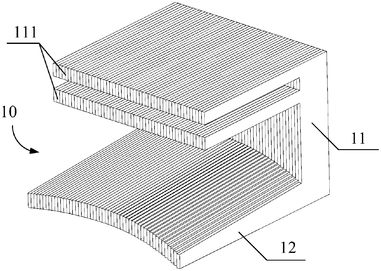
[0078] The difference from Embodiment 1 is that the stepped portion 121 is formed by a sheet structure, such as figure 2 shown.

[0079]Alternatively, the step portion 121 can also be formed by a sheet structure, and the width of each step portion 121 is small, so that the entire winding portion 12 can be as close as possible to a circular arc shape, thereby significantly improving the structural regularity of the product. Further improve motor performance.

Embodiment 3

[0081] The difference from Embodiment 1 or Embodiment 2 is that: both the tooth body 11 and the winding portion 12 have symmetrical structures, and are symmetrical about the same plane passing through the central axis of the stator.


PUM


Abstract

The invention provides a stator tooth, a stator and a motor. The stator tooth comprises a tooth body and a wire winding part; the tooth body is provided with a connecting part connected with the stator yoke of a stator; the wire winding part is connected with the tooth body and can be inserted into the inner side of the stator yoke, so that a wire winding groove for an annular winding to pass through can be defined between the winding part and the stator yoke; and in the circumferential direction of the stator, the wire winding parts gradually bends and extends towards a direction close to thecentral axis of the stator from the middle to the two sides. According to the stator tooth of the invention, the structure of the stator tooth is improved, and therefore, on one hand, an air gap between a rotor and a tooth part can be effectively reduced, so that the acting force between the stator and the permanent magnet rotor is enhanced; the rotor is driven to rotate, so that the performanceof a motor is effectively improved; and on the other hand, the volume of an accommodating cavity can be increased, a larger wire winding space is provided, and therefore, more windings can be wound, and the performance of the motor is improved.

Description

technical field [0001] The invention relates to the technical field of motors, in particular to a stator tooth, a stator including the stator tooth, and a motor including the stator. Background technique [0002] At present, in traditional motors with concentrated windings, there are ends of the windings, which will increase the material cost of the motor, and traditional motors need to wind windings on each stator tooth separately, resulting in low motor manufacturing efficiency. Contents of the invention [0003] In order to solve at least one of the above technical problems, an object of the present invention is to provide a stator tooth. [0004] Another object of the present invention is to provide a stator comprising the above stator teeth. [0005] Another object of the present invention is to provide a motor comprising the above stator. [0006] In order to achieve the above object, the technical solution of the first aspect of the present invention provides a st...

Claims


Application Information

Patent Timeline
Patent Type & Authority Applications(China)
IPC IPC(8): H02K1/14H02K1/16
CPCH02K1/146H02K1/16
Inventor 朱嘉东王飞
Owner WELLING WUHU MOTOR MFG
Why Eureka
Try Eureka