
Contact switch circuit

A contact switch and circuit technology, applied in electrical components, output power conversion devices, and AC power input into DC power output, etc., can solve the problems of high risk, reduced user experience, easy leakage and safety accidents, etc., to achieve safety Low sex, the effect of enhancing the experience

Inactive Publication Date: 2020-06-16
YUQUAN ELECTRONICS EQUIP CO LTD
View PDF0 Cites 0 Cited by
  • Summary
  • Abstract
  • Description
  • Claims
  • Application Information

AI Technical Summary

Problems solved by technology

[0002] In the field of electronic power technology, 220V (volt) alternating current is often used to power electronic equipment, and electronic equipment is generally powered by direct current, so it is necessary to rectify 220V alternating current. Rectification is used to supply power to electronic equipment, but this method is highly dangerous, and it is easy to leak electricity to cause safety accidents, which greatly reduces the user experience

Method used


Image

  • Contact switch circuit

Examples


Embodiment Construction

[0012] The present invention will be described in detail below in conjunction with the accompanying drawings and embodiments.

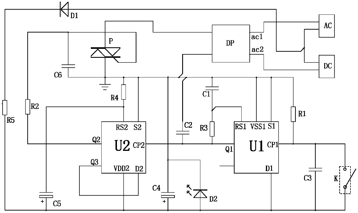
[0013] Such as figure 1 as shown, figure 1 It is a structural schematic diagram of the contact switch circuit of the present invention. The contact switch circuit includes an AC input terminal AC, a DC output terminal DC, a rectifier bridge DP, a thyristor P, a switch K, a first trigger U1, a first resistor R1 and a second trigger U2.

[0014] The AC input terminal AC is used to access 220V AC voltage.

[0015] The direct current output terminal DC is used for connecting with electronic equipment to provide power for the electronic equipment.

[0016] In this embodiment, the negative terminal of the AC input terminal AC is connected to the positive terminal of the DC output terminal DC, the positive terminal of the AC input terminal AC is connected to the positive input terminal ac1 of the rectifier bridge DP, and the negative terminal of the DC ou...


PUM


Abstract

The invention discloses a contact switch circuit. The contact switch circuit comprises an alternating current input end, a direct current output end, a rectifier bridge, a silicon controlled rectifier, a switch, a first trigger, a first resistor and a second trigger; the input end of the silicon controlled rectifier is connected with the anode output end of the rectifier bridge; the output end ofthe silicon controlled rectifier is connected with the cathode output end of the rectifier bridge; the pulse end of the first trigger is connected with one end of the switch; one end of the switch isgrounded through the first resistor; the pulse end of the second trigger is connected with the original code output end of the first trigger; the inverted code output end of the second trigger is connected with the data input end of the second trigger; the original code output end of the second trigger is connected with the control end of the silicon controlled rectifier through a second resistor;and the data input end of the first trigger is connected with the other end of the switch. By means of the contact switch circuit provided by the above technical schemes, 220V alternating current canbe controlled to supply power to electronic equipment through a small-current switch circuit, safety is high, and user experience is greatly improved.

Description

technical field [0001] The invention relates to the technical field of electronic power, in particular to a contact switch circuit. Background technique [0002] In the field of electronic power technology, 220V (volt) alternating current is often used to power electronic equipment, and electronic equipment is generally powered by direct current, so it is necessary to rectify 220V alternating current. Rectification is carried out to supply power to electronic equipment, but this method is highly dangerous, and it is easy to leak electricity to cause safety accidents, which greatly reduces the user experience. Contents of the invention [0003] The technical problem mainly solved by the present invention is to provide a contact switch circuit, which can use a small current switch circuit to control 220V alternating current to supply power to electronic equipment, which has low safety and greatly improves user experience. [0004] In order to solve the above-mentioned techn...

Claims


Application Information

Patent Timeline
IPC IPC(8): H02M7/155
CPCH02M7/1555
Inventor 宋翔宇
Owner YUQUAN ELECTRONICS EQUIP CO LTD
Features
  • Generate Ideas
  • Intellectual Property
  • Life Sciences
  • Materials
  • Tech Scout
  • Unparalleled Data Quality
  • Higher Quality Content
  • 60% Fewer Hallucinations
Learn More