

Method for producing stainless steel plate for fuel cell separator
A technology of stainless steel plates and fuel cells, which is applied to fuel cell parts, fuel cells, solid electrolyte fuel cells, etc., can solve the problems of increased contact resistance, reduced power generation efficiency, and large contact resistance, achieving low contact resistance, Low safety, practical and beneficial effect
- Summary
- Abstract
- Description
- Claims
- Application Information
AI Technical Summary
Problems solved by technology
Method used
Image

Examples
Embodiment 1
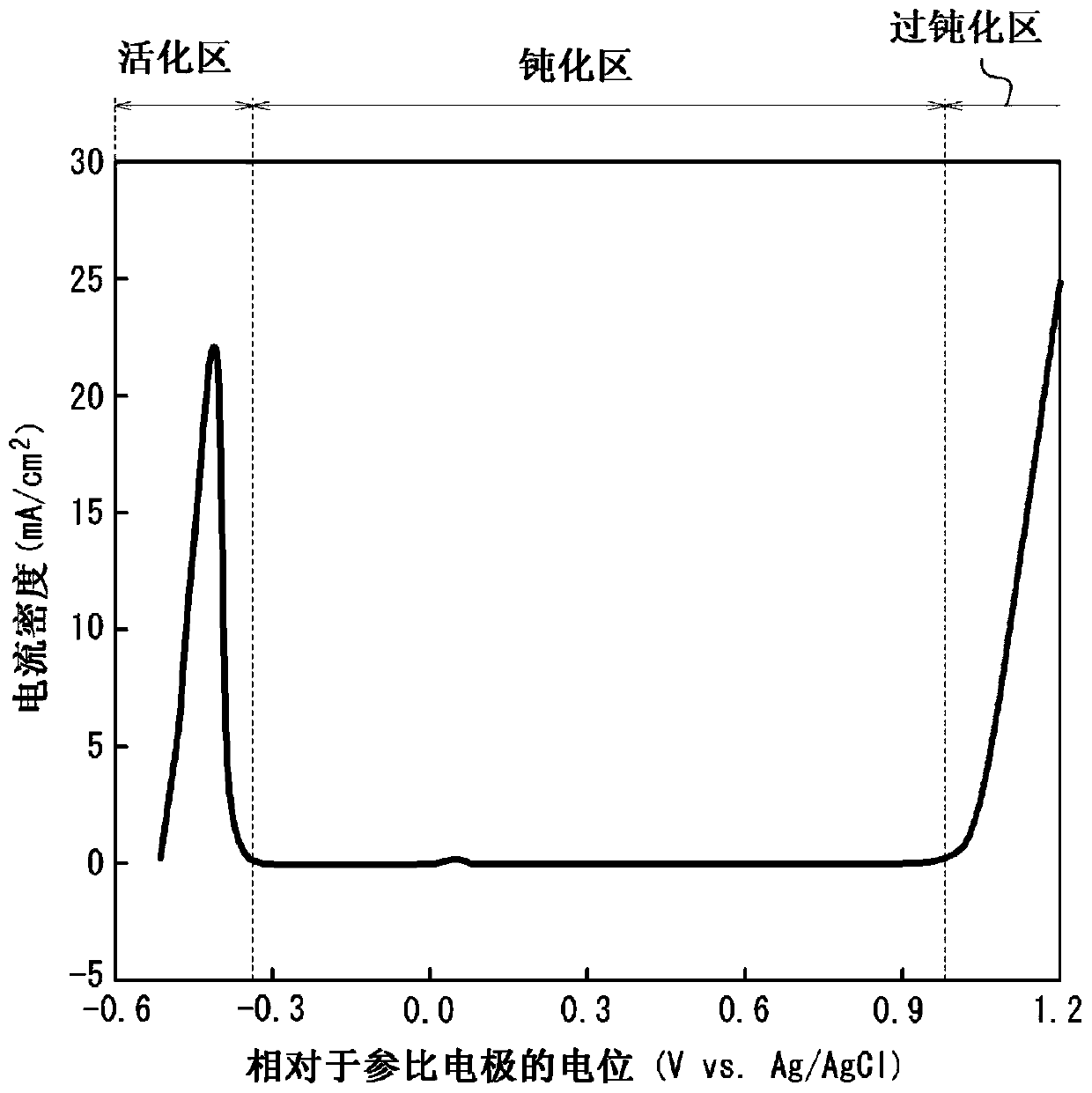
[0170] A stainless steel plate (bright annealed plate) having a plate thickness of 0.10 mm (bright annealed plate) having the composition described in Table 1 (the balance being Fe and unavoidable impurities) was prepared, and cathodic electrolysis was performed on the stainless steel plate under the conditions shown in Table 2. treatment to remove the oxide film formed on the surface of the steel sheet. Next, under the conditions shown in Table 2, electrolytic etching treatment was performed by potential control, and then, under the conditions shown in Table 2, dipping treatment was performed as a surface stabilization treatment to obtain a stainless steel plate for separators. It should be noted that the potentials in Table 2 are all relative to the potential of the reference electrode (Vvs. Ag / AgCl).
[0171] Here, when electrolytic etching is performed by potential control, Ag / AgCl is used as a reference electrode in advance, and each steel The anodic polarization curve w...
Embodiment 2
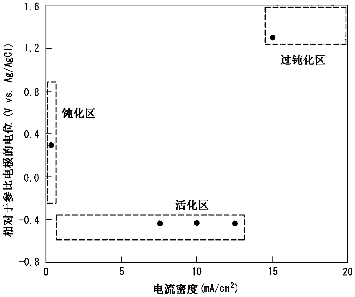
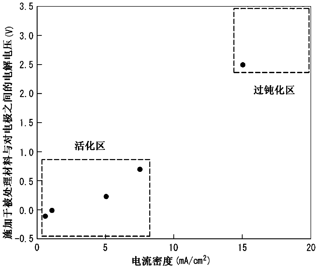
[0187] Prepare a stainless steel plate (bright annealed plate) with a plate thickness of 0.10 mm (bright annealed plate) having the component composition (the balance is Fe and unavoidable impurities) recorded in Table 1, and the stainless steel plate is subjected to the conditions shown in Table 3 and Table 4. Cathodic electrolytic treatment is performed to remove the oxide film formed on the surface of the steel sheet. Next, under the conditions shown in Table 3 and Table 4, an electrolytic etching treatment was carried out by current control, and then, under the conditions shown in Table 3 and Table 4, dipping treatment or electrolytic treatment was performed as a surface stabilization treatment to obtain Stainless steel plates for separators (It should be noted that the current densities in Tables 3 and 4 are values obtained by dividing the current flowing between the stainless steel plate to be processed and the counter electrode by the surface area of the processed ma...
PUM
 Abstract
Description
Claims
Application Information