Anchoring part and anchoring device

An anchor and an anchoring technology, applied in the field of medical devices, can solve problems such as easy displacement, and achieve the effects of increasing roughness, slowing down speed, and improving effectiveness

Active Publication Date: 2020-06-19
MICROPORT UROCARE
View PDF14 Cites 0 Cited by
  • Summary
  • Abstract
  • Description
  • Claims
  • Application Information

AI Technical Summary

Problems solved by technology

[0007] The purpose of the present invention is to provide an anchor and an anchor device to solve the problem that the existing anchor and anchor devices are easily displaced after implantation

Method used


Image

  • Anchoring part and anchoring device
  • Anchoring part and anchoring device
  • Anchoring part and anchoring device

Examples


Embodiment 1

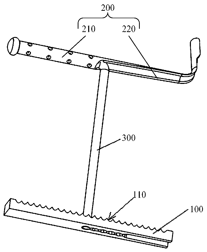
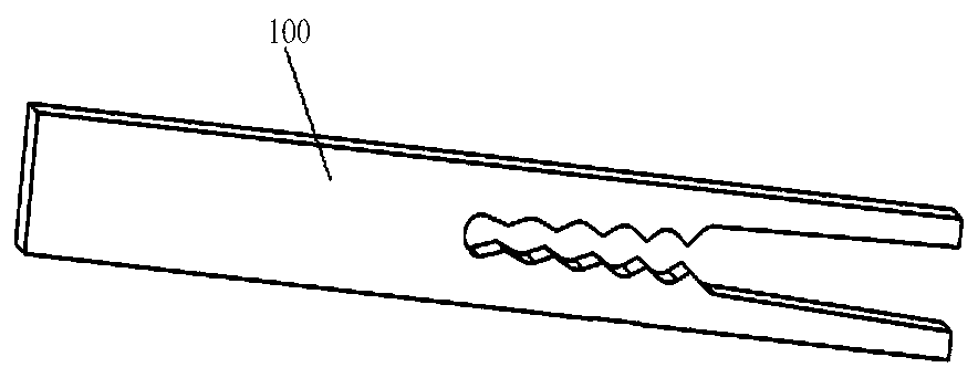
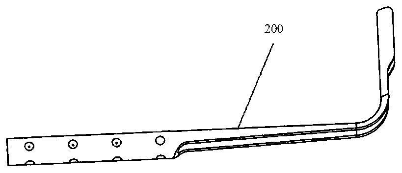
[0063] This embodiment provides an anchoring device. refer to figure 1 , figure 2 and image 3 , figure 1 is a schematic structural view of the anchoring device in Embodiment 1 of the present invention, figure 2 and image 3 They are schematic structural diagrams of the proximal anchor 100 and the distal anchor 200 in the anchoring device in Embodiment 1 of the present invention. The anchoring device includes the proximal anchor 100, the distal anchor 200 and the connector 300. The end anchor 100 includes a contact surface 110 and a non-contact surface. The contact surface 110 is used to contact the tissue. The contact surface 110 includes at least one concave portion and / or at least one convex portion. The concave portion or the convex portion includes but is not limited to Groove, pattern, frosted surface, etc. The connecting part 300 includes a first connecting part and a second connecting part extending from one end of the first connecting part, the second connecti...

Embodiment 2

[0083] This embodiment provides an anchoring device, and the anchoring device in this embodiment is a further improvement on the anchoring device in Embodiment 1. refer to Figure 14 and Figure 15 , Figure 14 and Figure 15 They are two structural diagrams of the proximal anchor 100 in the anchoring device in Embodiment 2 of the present invention. In this embodiment, the first protrusion 112 includes at least one second groove 113 .

[0084] Since the first protrusion 112 includes at least one second groove 113 . Therefore, the roughness of the contact surface 110 can be further increased, thereby further increasing the frictional resistance of the proximal anchor 100 relative to tissue movement, thereby further improving the wall-attachment performance of the proximal anchor 100 and reducing the relative resistance of the proximal anchor 100. The risk of tissue displacement further improves the anchoring stability of the anchoring device; the contact area between the co...

Embodiment 3

[0093] This embodiment provides an anchoring device. The difference between the anchoring device in this embodiment and the anchoring device in Embodiment 1 is that, refer to Figure 16 , Figure 16 It is a structural schematic diagram of the proximal anchor 100 in the anchoring device in the third embodiment of the present invention. In this embodiment, the concave portion includes a plurality of third grooves 115 provided on the contact surface 110 .

[0094] Such as Figure 16 As shown, a plurality of third grooves 115 are distributed in a dot shape. The shape of the third groove 115 on a section perpendicular to the contact surface 110 may be V-shaped, U-shaped or rectangular. The third groove 115 has a circular shape on a cross section parallel to the contact surface 110 . In other embodiments, the shape of the third groove 115 on a cross section parallel to the contact surface 110 may be an ellipse. Preferably, the plurality of third grooves 115 are evenly distribut...


PUM


Abstract

The invention provides an anchoring part and an anchoring device, and aims at solving the problem that existing anchoring parts and existing anchoring devices are prone to displacement after being implanted. The anchoring part comprises a contact surface and a non-contact surface, the contact surface is used for being in contact with a tissue, and the contact surface comprises at least one concavepart and / or at least one convex part. The anchoring device comprises a far-end anchor, a connecting part and the anchoring part, the connecting part is selectively connected to the anchoring part, and the connecting part is fixedly connected to the far-end anchor. According to the anchoring part and the anchoring device in the invention, the anchoring part comprises the contact surface and the non-contact surface, and the contact surface comprises at least one concave part and / or at least one convex part, so that the roughness of the contact surface can be greater than that of the non-contactsurface, the adherence performance of the anchoring part can be improved, the risk of displacement of the anchoring part relative to the tissue is reduced, and the anchoring stability of the anchoring device is improved.

Description

[0001] This case is a divisional application, the application number of the original application is 201811460229.8, the application date is November 30, 2018, and the name is an anchor and an anchor device. technical field [0002] The invention relates to the technical field of medical instruments, in particular to an anchoring piece and an anchoring device. Background technique [0003] Benign prostatic hyperplasia is the most common benign disease causing voiding disorders in middle-aged and elderly men. The main manifestations are histological hyperplasia of prostatic stroma and glandular components, anatomical prostatic enlargement, clinical symptoms dominated by lower urinary tract symptoms, and urodynamic bladder outlet obstruction. [0004] In addition to drug therapy, the surgical methods for benign prostatic hyperplasia include the following: (1) transurethral resection of the prostate; (2) suprapubic or retropubic prostatectomy; (3) laser enucleation or resection ...

Claims


Application Information

Patent Timeline
Patent Type & Authority Applications(China)
IPC IPC(8): A61F2/00A61M31/00
CPCA61F2/0059A61M31/00A61M2210/166A61F2250/0067A61M2210/005
Inventor 汪振傅振中富佳伟阙亦云章艺
Owner MICROPORT UROCARE
Why Eureka
Try Eureka