Skull defect protective device

A protective device and skull technology, applied in the field of medical devices, can solve the problems of inapplicability of protective caps, increased discomfort of patients, and improvement of infected wounds, and achieve the effects of reducing the risk of infected wounds, increasing the scope of use, and avoiding random shaking

Inactive Publication Date: 2020-06-19
马全锋
View PDF6 Cites 2 Cited by
  • Summary
  • Abstract
  • Description
  • Claims
  • Application Information

AI Technical Summary

Problems solved by technology

[0005] The skull defect protective cap in the above prior art has the following disadvantages in actual use: the protective cap cannot be used by patients with different head sizes and bone window positions of different skulls, that is, the versatility is poor; at the same time, after wearing, The gap between it and the skin on the head is narrow, that is, the air permeability is poor, which causes the patient to increase sweat secretion after wearing it, and increases the risk of bacterial growth and infection of the wound; in addition, after wearing it, the silicone material inside the cover is relatively stable. Poor, easy to shake, causing increased discomfort to patients, and easy to cause secondary injuries, in view of the above defects in the prior art, a skull defect protection device is proposed

Method used


Image

  • Skull defect protective device
  • Skull defect protective device
  • Skull defect protective device

Examples


Embodiment Construction

[0029] The following will clearly and completely describe the technical solutions in the embodiments of the present invention with reference to the accompanying drawings in the embodiments of the present invention. Obviously, the described embodiments are only some, not all, embodiments of the present invention.

[0030] In describing the present invention, it should be understood that the terms "upper", "lower", "front", "rear", "left", "right", "top", "bottom", "inner", " The orientation or positional relationship indicated by "outside", etc. is based on the orientation or positional relationship shown in the drawings, and is only for the convenience of describing the present invention and simplifying the description, rather than indicating or implying that the referred device or element must have a specific orientation, so as to Specific orientation configurations and operations, therefore, are not to be construed as limitations on the invention.

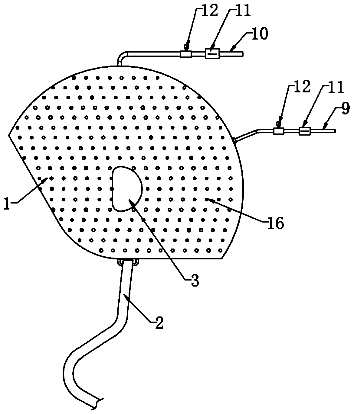
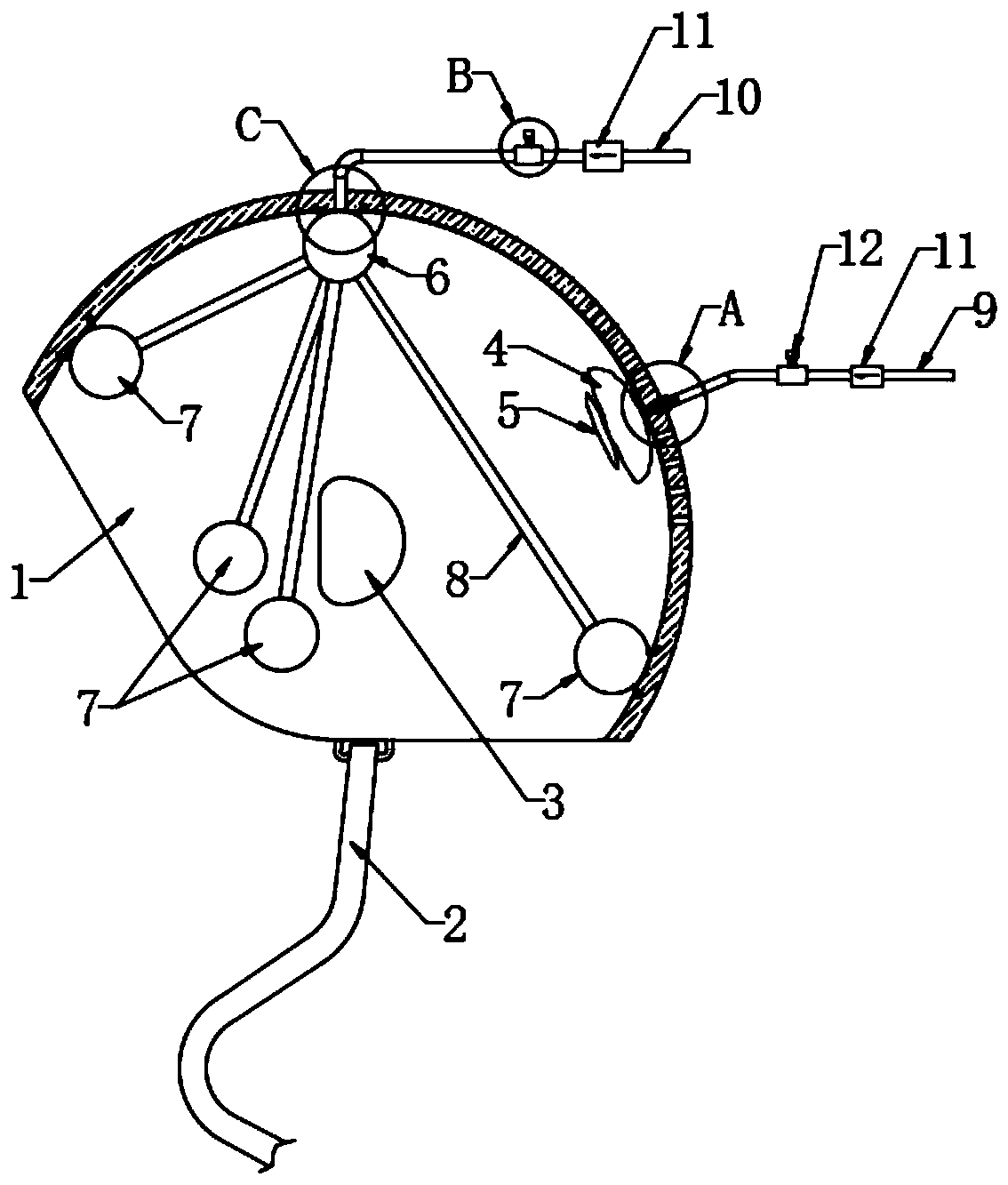
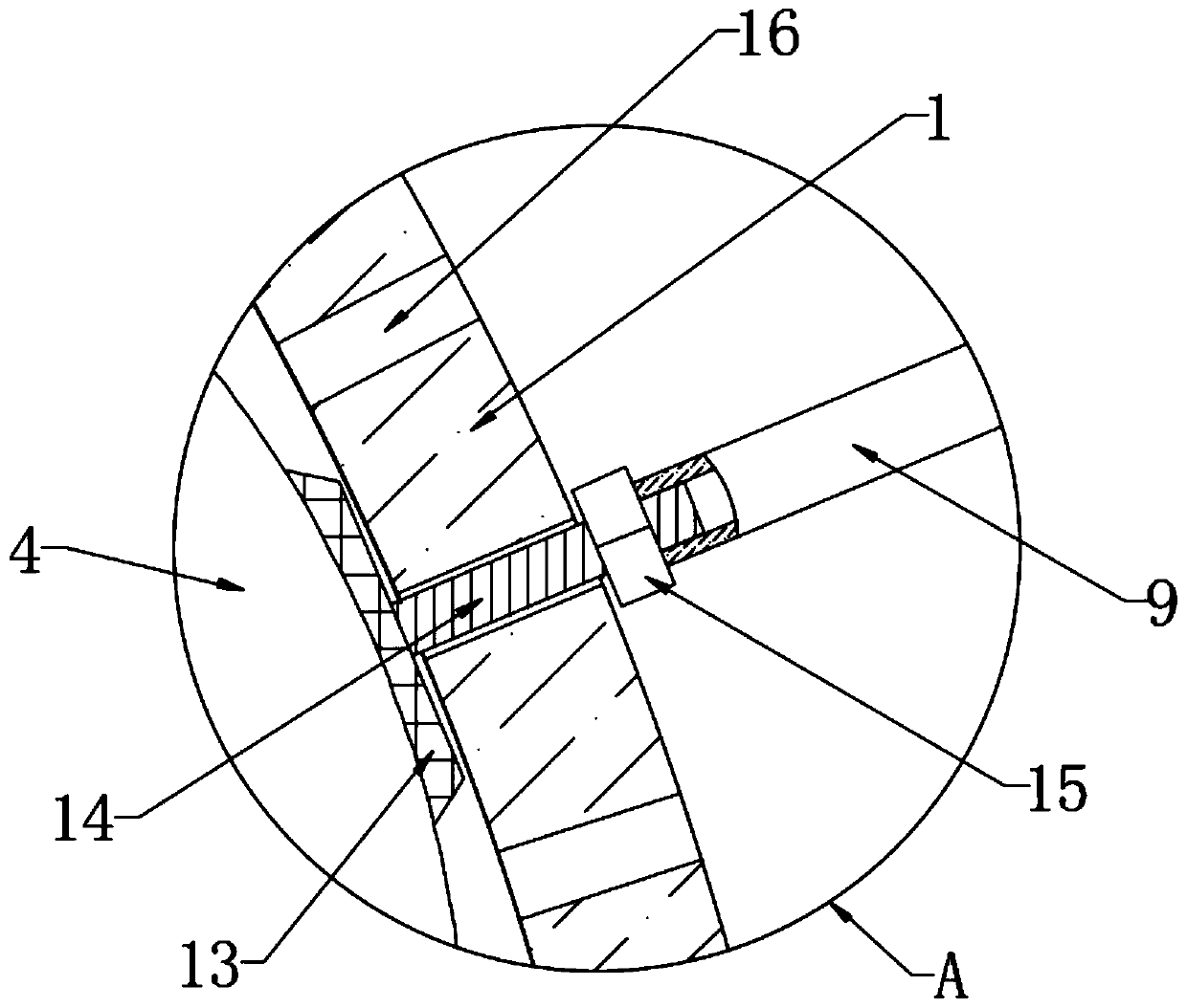
[0031] refer to Figure ...


PUM


Abstract

The invention discloses a skull defect protective device. The skull defect protective device comprises a hood, a first airbag and a silica gel shield body; both the first airbag and the silica gel shield body are positioned on the inner side wall of the hood, and the silica gel shield body is fixed at the front side of the first airbag; a plurality of air holes are uniformly formed in a penetrating manner in the side wall of the hood; a rubber mat is fixed at one side, away from the silica gel shield body, of the first airbag; a second threaded pipe is fixed at one side, away from the first airbag, of the rubber mat; one end, away from the rubber mat, of the second threaded pipe extends to the outside of the hood through one air hole and is in threaded connection with a sealed tube; the sealed tube and a first air tube are fixed; and an air exhaust device and a check valve are sequentially mounted at one end, away from the hood, of the first air tube. The protective device in the scheme can be suitable for patients with different head sizes and different skull window positions to wear for use; after the skull defect protective device is worn, stability, air permeability, safety andcomfort of the skull defect protective device are all greatly improved; and the skull defect protective device is more suitable to use and easier to accept by patients.

Description

technical field [0001] The invention relates to the technical field of medical devices, in particular to a skull defect protection device. Background technique [0002] Craniotomy and decompressive craniectomy are often performed to rescue patients in neurosurgery. This operation can relieve life-threatening emergencies such as increased intracranial pressure and cerebral hernia caused by severe traumatic brain injury, intracranial hematoma, cerebral edema, cerebral hemorrhage and other diseases. . Such patients are often in critical condition and have a long hospital stay. Generally, cranioplasty is considered 3-6 months after the initial operation. [0003] The skull defect area is generally located in the frontotemporal region, and its diameter is greater than 8cm, which often causes severe skull deformity and directly affects the physiological balance of intracranial pressure. It collapses when sitting, swells when lying down, is concave in the morning and protrudes at...

Claims


Application Information

Patent Timeline
IPC IPC(8): A61F13/12A61F13/00
CPCA61F13/12A61F2013/00255A61F13/01046
Inventor 马全锋
Owner 马全锋
Why Eureka
Try Eureka