Spraying device for steel pipe surface

A technology for surface spraying and steel pipes, applied in the direction of spraying devices, liquid spraying devices, etc., can solve the problems of shortening the service life of steel pipes and affecting the anti-corrosion effect of steel pipe surfaces, etc., to improve consistency, facilitate reuse, and improve spraying quality Effect

Inactive Publication Date: 2020-06-19
严白双
View PDF6 Cites 6 Cited by
  • Summary
  • Abstract
  • Description
  • Claims
  • Application Information

AI Technical Summary

Problems solved by technology

[0002] Steel pipes play an important role in the transportation of crude oil, natural gas, gas and other substances. Under normal use, steel pipes will undergo oxidation reactions with air and moisture in the soil, which will shorten the service life of steel pipes. Therefore, the steel pipes produced now will undergo anti-corrosion treatment. , the existing anti-corrosion treatment is generally to move the steel pipe to the spraying box through the conveyor belt, and the paint nozzle in the spraying box sprays the steel pipe to achieve the anti-corrosion effect, but this way makes the steel pipe and the conveyor belt The contact side will be blocked , without painting, which will affect the anti-corrosion effect of the steel pipe surface, so it is urgent to develop a steel pipe surface spraying device to solve the above problems and facilitate market promotion and application

Method used


Image

  • Spraying device for steel pipe surface
  • Spraying device for steel pipe surface
  • Spraying device for steel pipe surface

Examples


Embodiment Construction

[0022] The following will clearly and completely describe the technical solutions in the embodiments of the present invention with reference to the accompanying drawings in the embodiments of the present invention. Obviously, the described embodiments are only some, not all, embodiments of the present invention. Based on the embodiments of the present invention, all other embodiments obtained by persons of ordinary skill in the art without making creative efforts belong to the protection scope of the present invention.

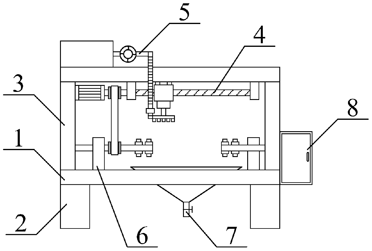
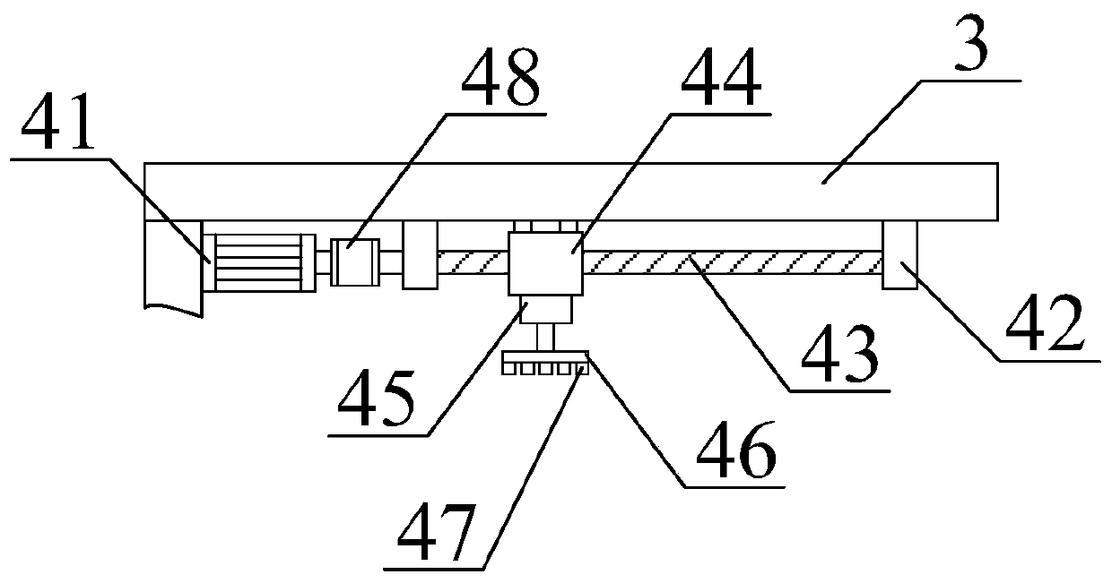
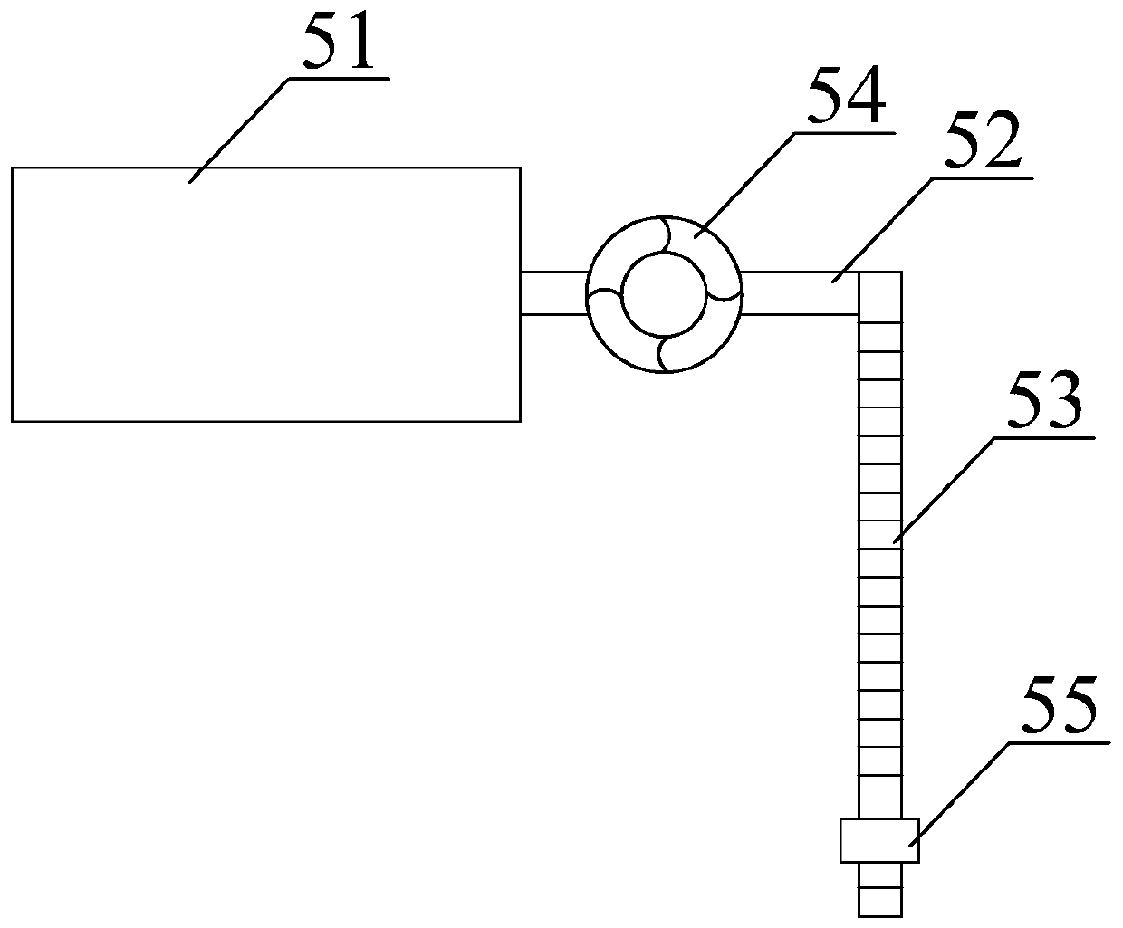
[0023] see Figure 1-4 , the present invention provides a technical solution: a steel pipe surface spraying device, such as figure 1 As shown, it includes a workbench 1, a support foot 2, a bracket 3, a spraying assembly 4, a feeding assembly 5, a support assembly 6, a waste bin 7 and an electric control cabinet 8, and four support feet 2 are used, and the support foot 2 It is fixed on the bottom four corners of the workbench 1 by bolts; the support 3 is fixe...


PUM


Abstract

The invention discloses a spraying device for a steel pipe surface. The spraying device comprises a workbench, a support foot, a bracket, a spraying assembly, a feeding assembly, a support assembly, awaste box and an electric control cabinet. By setting the support assembly, one end of the steel pipe is sleeved on a second electric pushing rod, the other end of the steel pipe is sleeved on a third electric pushing rod, the second electric pushing rod and the third electric pushing rod are powered to run and extend to support the steel pipe, the support is carried out by an inner support method, and during the spraying process, the outer surface of the steel pipe can be sprayed without dead angles to improve the spraying quality of the steel pipe; by setting the spraying assembly, a mobilemotor is powered to run so that a nut seat is moved to one end of the steel pipe, the first electric pushing rod is powered to run so that a nozzle stretches above the steel pipe, a driving pulley drives a driven pulley to rotate, so that the movement speed of the nut seat is consistent with the rotational linear speed of a first rotary rod, the consistent spraying speed and the rotating speed ofthe steel pipe are ensured, and the consistency of the steel pipe spraying quality is improved.

Description

technical field [0001] The invention relates to the technical field of spraying equipment, in particular to a steel pipe surface spraying device. Background technique [0002] Steel pipes play an important role in the transportation of crude oil, natural gas, gas and other substances. Under normal use, steel pipes will undergo oxidation reactions with air and moisture in the soil, which will shorten the service life of steel pipes. Therefore, the steel pipes produced now will undergo anti-corrosion treatment. , the existing anti-corrosion treatment is generally to move the steel pipe to the spraying box through the conveyor belt, and the paint nozzle in the spraying box sprays the steel pipe to achieve the anti-corrosion effect, but this way makes the steel pipe and the conveyor belt The contact side will be blocked , without painting, thereby affecting the anti-corrosion effect of the steel pipe surface, so it is urgent to develop a steel pipe surface spraying device to sol...

Claims


Application Information

Patent Timeline
Patent Type & Authority Applications(China)
IPC IPC(8): B05B9/04B05B13/02B05B14/00B05B15/70
CPCB05B9/0403B05B13/0214B05B13/0228B05B14/00B05B15/70
Inventor 严白双
Owner 严白双
Why Eureka
Try Eureka