Synchronous spraying and curing processing method for pipelines arranged in parallel

A processing method and pipeline technology, applied in coating, spraying device, device for coating liquid on the surface, etc., can solve the problems of inability to solve spraying, reduced utilization rate of plant area, excessive length of spray gun, etc., so as to reduce the cost of plant construction , The effect of reducing equipment investment costs and improving production efficiency

Active Publication Date: 2016-03-23
青岛豪德博尔实业有限公司
View PDF4 Cites 17 Cited by
  • Summary
  • Abstract
  • Description
  • Claims
  • Application Information

AI Technical Summary

Problems solved by technology

However, the defects are as follows: 1. The steel pipe is fixed, resulting in uneven outer spraying, that is, the bottom spraying layer is thin. 2. The inner and outer spray guns move from one side to the other side, and then reset; then the next steel pipe can be sprayed. The efficiency is not high, and the powder recycling is insufficient, and the waste of plastic coating powder is serious
3. The movable support is pulled by the steel wire. The defects are as follows. The support is located in the pipe, which is easy to cause scratches on the spraying position. 4. The steel wire rope traction makes the movable support difficult to operate when it is taken out of the pipe end or placed at the starting position of the other end.
5. There are many problems in synchronous heating and curing, because the electromagnetic heating cylinder cannot cover the whole pipeline, and the electromagnetic heating cylinder is constantly moving, resulting in uneven heating and poor curing effect
6. When curing, the curing box is usually located on the same straight line as the pipeline, and the sprayed pipeline is directly sent into the curing box through a walking trolley, and is heated and dried by gas to cure. This structure requires a long production line to produce 6 meters For example, the length of the spray gun is 6 meters, the length of the spraying line is 6 meters, and the length of the curing box is 6 meters. In addition to the distance from the pipe, the length of a line is often 25 meters. If the pipe with a higher length is processed, the length of the plant is required longer
However, in reality, the distance between workshops cannot be adjusted. Therefore, the crane is usually used to continuously lift steel pipes, hoist them up, and lower them down, etc., which increases the probability of safety accidents.
[0005] In order to solve the above technical problems, some rigid spray guns have appeared on the market, that is, the spray gun is erected at the end of the steel pipe, the spray gun is pushed forward by the moving trolley, and the track is laid under the moving trolley. However, the length of the spray gun is too long when moving from one end of the pipe to the other end. It leads to vibration at the end and uneven powder spraying. Moreover, the excessively long pipeline will inevitably increase the track distance of the moving trolley supporting the spray gun, increase the occupied area, and greatly reduce the utilization rate of the plant area.
However, reducing the length of the rigid spray gun can not solve the long pipeline (such as more than 8 meters) spraying

Method used


Image

  • Synchronous spraying and curing processing method for pipelines arranged in parallel
  • Synchronous spraying and curing processing method for pipelines arranged in parallel
  • Synchronous spraying and curing processing method for pipelines arranged in parallel

Examples


Embodiment Construction

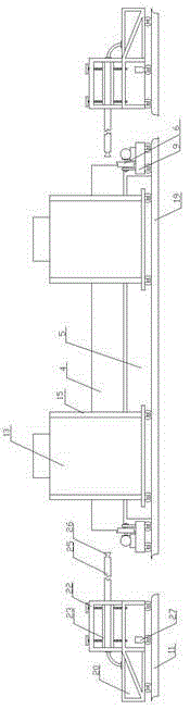
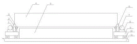
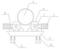
[0040] The present invention will be described below in conjunction with the accompanying drawings. Such as Figure 1-Figure 9 as shown, figure 1 It is a structural schematic diagram of the electrostatic spraying line of the present invention. figure 2 It is a structural schematic diagram of the steel pipe conveying device of the present invention. image 3 for figure 2 side view. Figure 4 It is a structural schematic diagram of the external spraying device of the present invention during operation. Figure 5 It is a structural schematic diagram of the walking box of the inner spray gun of the present invention. Figure 6 It is a schematic top view of the powder receiving tank of the present invention. Figure 7 It is a schematic diagram of the state of recovered powder in the powder receiving tank of the present invention. Figure 8 It is a state diagram before use of the pipe side-by-side moving device of the present invention. Figure 9 It is a state diagram of t...


PUM


Abstract

The invention discloses a synchronous spraying and curing processing method for pipelines arranged in parallel. The method includes the following steps that A, steel pipes are thrown into an acid pickling pond to be subjected to acid pickling for removing rust; B, the steel pipes subjected to acid pickling are cleanly flushed through clear water and then are dried for standby application; C, the steel pipes obtained in the step B are subjected to medium frequency heating; D, the interiors and the exteriors of the steel pipes are subjected to synchronous plastic coating through an electrostatic spraying method; E, heating and curing are carried out, and the pipelines are moved side by side before being cured; and F, natural cooling is conducted. In the step D, the plastic coating operation is carried out through an electrostatic spraying line, and the electrostatic spraying line comprises a steel pipe conveying device, an external spraying device, an internal spraying device, a powder recovery device and a pipeline side-by-side moving device. The method is simple, using is convenient, and production efficiency can be improved; a spray gun can be prevented from vibrating, powder is uniformly sprayed, and the powder utilization rate is high; the pipelines do not need to be lifted repeatedly and can be moved side by side.

Description

Technical field: [0001] The invention relates to the technical field of pipelines, in particular to a processing method for synchronous spraying and curing of pipelines arranged in parallel. Background technique: [0002] The coated pipes of steel pipes include galvanized pipes, aluminum-plated pipes, chrome-plated pipes, aluminized pipes and steel pipes with other alloy layers. Coated tubes include outer coated tubes, inner coated tubes, and inner and outer coated tubes. Commonly used coatings include plastics, epoxy resins, coal tar epoxy resins, and various glass-type anti-corrosion coating materials. The coated steel pipe is made by coating plastic on the inner wall (or outer wall if necessary) by powder fusion spraying technology, and its performance is excellent. Compared with galvanized pipe, it has the advantages of anti-corrosion, no rust, no fouling, smooth and smooth, clean and non-toxic, and long service life. According to tests, the service life of the stee...

Claims


Application Information

Patent Timeline
Patent Type & Authority Applications(China)
IPC IPC(8): B05D1/06B05D3/10B05D3/02B05B13/02B05B15/04B05B13/04B05B13/06
CPCB05B13/0221B05B13/041B05B13/06B05B14/10B05D1/06B05D3/0218B05D3/102
Inventor 付希波
Owner 青岛豪德博尔实业有限公司
Why Eureka
Try Eureka