SLM forming method based on intelligent scanning path planning and product

A scanning path, laser scanning path technology, applied in the SLM forming method and product field based on intelligent scanning path planning, can solve the problems of no fundamental change in scanning strategy, unoptimized scanning method, and unchanged scanning method, so as to avoid heat Concentration, avoiding temperature gradient, and improving the effect of forming accuracy

Inactive Publication Date: 2020-06-19
HUAZHONG UNIV OF SCI & TECH
View PDF9 Cites 16 Cited by
  • Summary
  • Abstract
  • Description
  • Claims
  • Application Information

AI Technical Summary

Problems solved by technology

At present, there are many related patents. By partitioning each layer of slices, different areas are scanned with angle changes to reduce the possibility of thermal stress concentration, but the essence of the scanning method remains unchanged (such as scanning distance and scanning route). Unable to intelligently optimize the scanning strategy by identifying local special geometric features
For example, the patent CN201711190187.6 proposes a multi-partition scanning method, which divides each slice into multiple regions, and uses parallel lines with different angles to scan each region line by line, which can make the stress generated by laser scanning more dispersed and reduce warping The possibility of deformation, but there is no fundamental change in the scanning strategy of each area, which will still generate large thermal stress for parts with special geometric features (such as sharp corners, thin walls, lattice structures, etc.); patent CN201811632180. In X, a partitioned serpentine scanning planning method is proposed to effectively avoid excessive thermal stress caused by large-format and large-spot processing. However, this serpentine scanning method is used in each area, and the scanning method cannot be optimized based on special geometric features.

Method used


Image

  • SLM forming method based on intelligent scanning path planning and product
  • SLM forming method based on intelligent scanning path planning and product
  • SLM forming method based on intelligent scanning path planning and product

Examples


Embodiment Construction

[0034] In order to make the object, technical solution and advantages of the present invention clearer, the present invention will be further described in detail below in conjunction with the accompanying drawings and embodiments. It should be understood that the specific embodiments described here are only used to explain the present invention, not to limit the present invention. In addition, the technical features involved in the various embodiments of the present invention described below can be combined with each other as long as they do not constitute a conflict with each other.

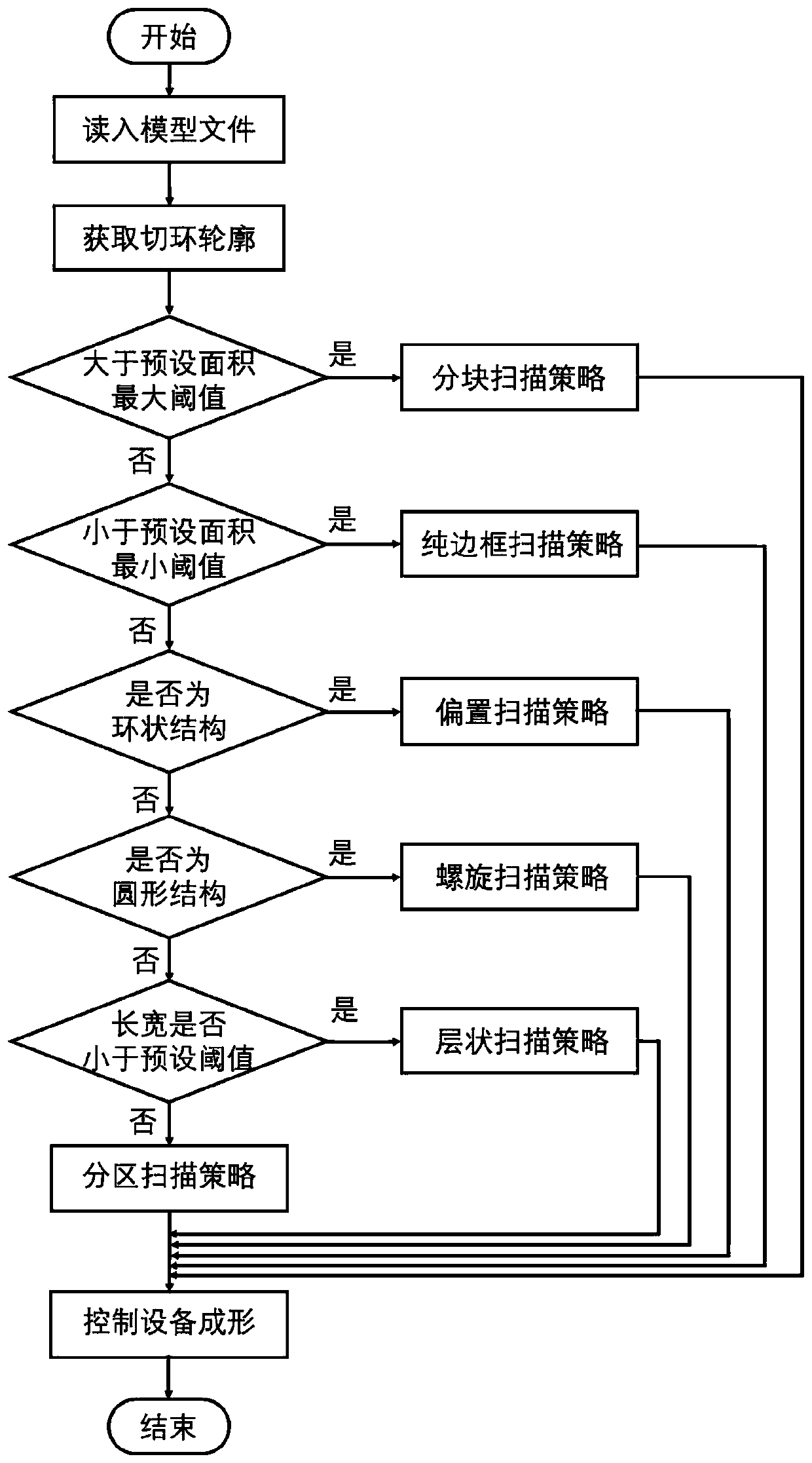
[0035] Such as figure 1 As shown, a kind of SLM forming method based on intelligent scanning path planning provided by the present invention, its steps are as follows:

[0036] S1, performing layered slicing processing on the part three-dimensional model file (such as an STL format file), that is, cutting it according to a fixed layer thickness, and obtaining the cutting ring profile of each la...


PUM


Abstract

The invention belongs to the related technical field of additive manufacturing, and particularly discloses an SLM forming method based on intelligent scanning path planning and a product. The method comprises the following steps that (a), when a three-dimensional model of a to-be-formed part is sliced, part contour information included in a plurality of slice layers and each slice layer are obtained; (b) for each slice layer, the slice contour is divided into a plurality of areas according to the part contour information in the slice layer, and the geometric feature of each area is obtained; (c), a laser scanning path corresponding to each area is planned according to the geometrical characteristics of each area, and a scanning sequence of each area is set so as to obtain the scanning sequences and the laser scanning paths of all the areas in each slice layer; and (d), the slice layers of the to-be-formed part are machined layer by layer according to the scanning sequences and the scanning paths, and the needed part is obtained. According to the SLM forming method based on intelligent scanning path planning and the product, the problem of difference of process requirements of different characteristics of the same part during SLM forming is solved, and the quality of the formed part is improved.

Description

technical field [0001] The invention belongs to the technical field related to additive manufacturing, and more specifically relates to an SLM forming method and product based on intelligent scanning path planning. Background technique [0002] Selective Laser Melting (SLM) is one of the fastest-growing additive manufacturing technologies in recent years. It uses metal powder (such as stainless steel, titanium alloy, copper alloy, etc.) For planning information, high-power laser is used to scan layer by layer, so that the metal powder in the scanned area is melted and solidified to form, and the unscanned area is still in a discrete state, thus forming layer by layer. The method is not limited by the complexity of the formed parts, does not need special matching tooling molds, and has good mechanical effects and high precision of the formed parts, so it has a good application prospect. [0003] In the SLM forming process, laser parameters play a vital role in the quality of...

Claims


Application Information

Patent Timeline
Patent Type & Authority Applications(China)
IPC IPC(8): B22F3/105B33Y10/00B33Y50/02B33Y80/00
CPCB33Y10/00B33Y50/02B33Y80/00B22F10/00B22F10/28B22F10/366B22F10/38Y02P10/25
Inventor 魏青松刘演冰李继康程坦李想张少博
Owner HUAZHONG UNIV OF SCI & TECH
Why Eureka
Try Eureka