Ball head milling cutter, ball head double-edged milling cutter and processing method

A ball-end milling cutter and ball-end technology, which is applied in the direction of milling cutters, metal processing equipment, manufacturing tools, etc., can solve the problems of affecting the service life of the tool and the poor quality of the processed surface, so as to prolong the life of the milling cutter, improve the quality, and improve the The effect of longevity

Pending Publication Date: 2020-06-19
SHENZHEN JINZHOU PRECISION TECH
View PDF0 Cites 1 Cited by
  • Summary
  • Abstract
  • Description
  • Claims
  • Application Information

AI Technical Summary

Problems solved by technology

In this way, the extrusion rather than the cutting action will result in poor surface quality at the corresponding position of the workpiece, and a large amount of heat will be generated at the ball head due to extrusion friction, which will affect the service life of the tool

Method used


Image

  • Ball head milling cutter, ball head double-edged milling cutter and processing method
  • Ball head milling cutter, ball head double-edged milling cutter and processing method
  • Ball head milling cutter, ball head double-edged milling cutter and processing method

Examples


Embodiment 1

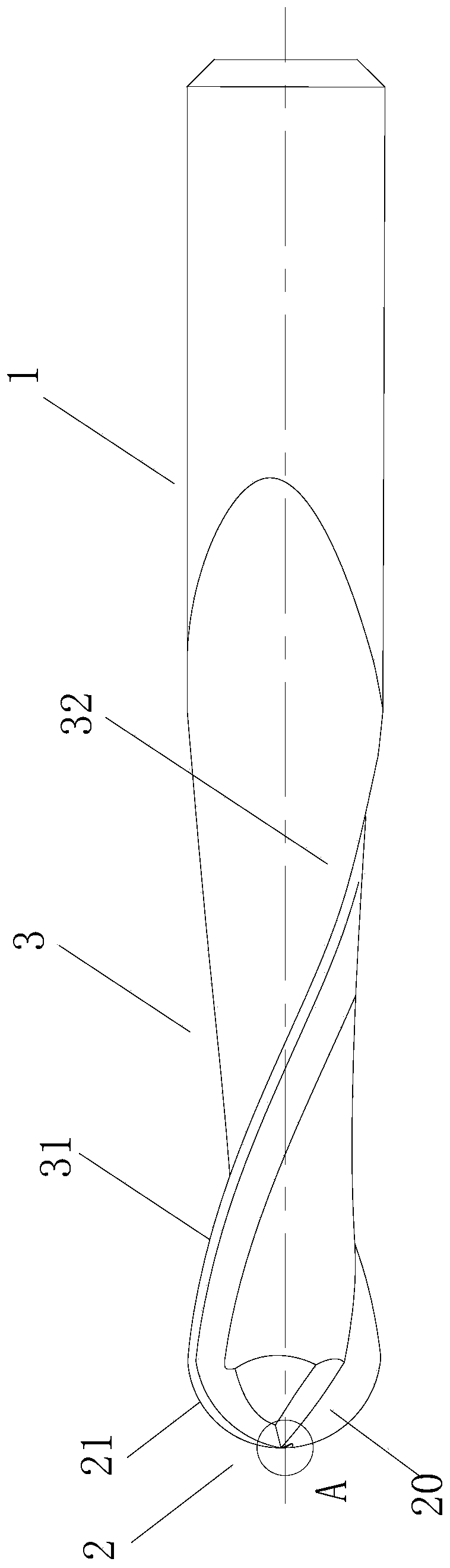
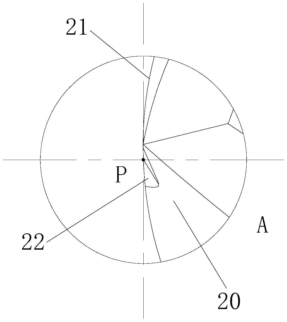
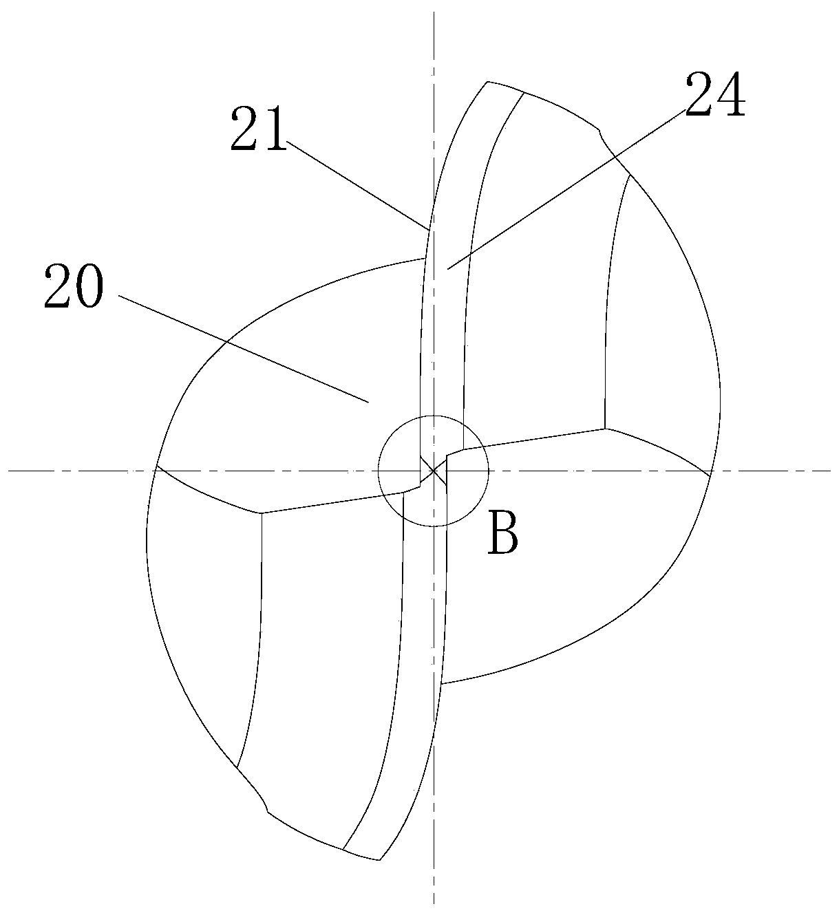
[0077] Such as Figure 1 to Figure 4 , Figure 7 with Figure 8 As shown, this embodiment corresponds to the above-mentioned arrangement mode (4) of the core cutting edge 23. There are two ball-end cutting edges 21, and a boundary line 26 is formed after the flank faces 24 of the two ball-end cutting edges 21 intersect. 26 passes through the ball vertex P of the ball cutting part 2, and the center of the boundary line 26 coincides with the ball vertex P, and there are two core grooves 22, wherein the ball cutting edge 21 and the core groove 22 are about the axis of the tool body 1 Symmetrically distributed along the circumferential direction, two ball-end cutting edges 21 are arranged at intervals of 180° along the circumference, and the first groove wall 221 of each core groove 22 intersects with the flank surface 24 of the corresponding ball-end cutting edge 21 to obtain two The core blade 23, wherein, the ball point apex P divides the boundary line 26 into two line segmen...

Embodiment 2

[0079] Such as Figure 1 to Figure 3 , Figure 5 , Figure 7 with Figure 8 As shown, this embodiment corresponds to the arrangement method (8) of the above-mentioned core cutting edge 23, and there are two ball-end cutting edges 21. Coincidentally, the other end point of each core edge 23 is located on the corresponding ball-end cutting edge 21 , and there is an included angle between the core edge 23 and the boundary line 26 .

Embodiment 3

[0081] This embodiment corresponds to the arrangement method (4) of the above-mentioned core blade 23. There are two ball-end cutting edges 21. The difference from Embodiment 1 is that there is only one core groove 22, and the ball-end cutting edge 21 is about the axis of the tool body 1. The center is distributed symmetrically along the circumferential direction, and the two ball-end cutting edges 21 are arranged at intervals of 180° along the circumferential direction. The first groove wall 221 of the core groove 22 intersects with the flank surface 24 of any one of the ball-end cutting edges 21 to obtain a core edge 23 . Wherein, in an ideal state, the end point of the core edge 23 near the vertex P of the ball will coincide with the vertex P of the ball. However, in practical applications, due to the influence of processing conditions (such as the thickness of the grinding wheel), the end points of the core cutting edge 23 may not coincide with the apex P of the ball head,...


PUM


Abstract

The invention is suitable for the technical field of cutting tools, and discloses a ball head milling cutter, a ball head double-edged milling cutter and a processing method. The ball head milling cutter comprises a tool main body, wherein one end of the tool main body is provided with a ball head cutting part; the ball head cutting part comprises at least two ball head cutting edges which are arranged on the axial end surface of the tool main body; the ball head cutting part is provided with at least one core slot; one slot wall of the core slot is crossed with the rear cutter surface of thecorresponding ball head cutting edge to form a core edge; one end of the core edge is close to a ball head vertex of the ball head cutting part; or one end of the core edge is superposed with the ballhead vertex; the other end of the core edge is close to the corresponding ball head cutting edge; or the other end of the core edge is connected to the corresponding ball head cutting edge. The ballhead milling cutter, the ball head double-edged milling cutter and the processing method provided by the invention can effectively improve quality of a workpiece processing surface, and further can reduce heat generated while the ball head cutting part is processed.

Description

technical field [0001] The invention belongs to the technical field of cutting tools, and in particular relates to a ball-end milling cutter, a ball-end double-edged milling cutter and a processing method. Background technique [0002] The ball head of the existing ball end milling cutter has no cutting edge near the axis. The linear velocity of the general ball end milling cutter at the ball head is zero. When using the ball end milling cutter for end milling, the rotation of the ball head can be approximately considered Extrusion and scraping processing is carried out in the axial center area, that is, the position close to the axial center is not the cutting action, but the material removal achieved by extrusion. In this way, extrusion instead of cutting will result in poor surface quality at the corresponding position of the workpiece, and a large amount of heat will be generated at the ball head due to extrusion friction, which will affect the service life of the tool. ...

Claims


Application Information

Patent Timeline
Patent Type & Authority Applications(China)
IPC IPC(8): B23C5/10
CPCB23C5/1018
Inventor 厉学广
Owner SHENZHEN JINZHOU PRECISION TECH
Why Eureka
Try Eureka