Tool adjusting mechanism for plate shearing machine

A technology of adjusting mechanism and shearing machine, which is applied to the accessories of shearing machine, shearing machine equipment, shearing device, etc. The effect of flexural modulus

Pending Publication Date: 2020-06-19
惠州市积裕金属制品有限公司
View PDF1 Cites 3 Cited by
  • Summary
  • Abstract
  • Description
  • Claims
  • Application Information

AI Technical Summary

Problems solved by technology

But the blade gap adjustment device of the above-mentioned shearing machine still has some shortcomings, as: although the above-mentioned adjustment device can adjust the gap between the upper blade and the lower blade, it adopts the form of a mechanical torsion shaft, although it can be adjusted gap, but the structural stability of the upper blade is affected, making it easy for the upper blade to change the gap after the gap is adjusted

Method used


Image

  • Tool adjusting mechanism for plate shearing machine
  • Tool adjusting mechanism for plate shearing machine
  • Tool adjusting mechanism for plate shearing machine

Examples


Embodiment 1

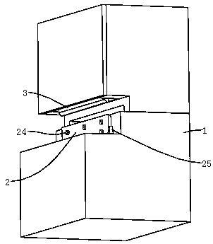
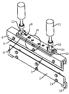
[0027] refer to figure 1 , figure 2 and image 3 , the knife adjustment mechanism for the shearing machine, including the lower blade 2 installed and fixed in the shearing machine body 1 and the upper blade 3 for matching and cutting with the lower blade 2; The blade 3 can be pressed down and the gap can be adjusted, and the top of the upper blade 3 is snapped into the opening of the U-shaped clamping plate 4, wherein the U-shaped clamping plate 4 and the upper blade 3 are connected by four first locking bolts 5 , a first connecting plate 6 is welded and fixed on the top of the 匚-shaped clamping plate 4, and a second connecting plate 8 is installed and fixed horizontally above the first connecting plate 6 through two second locking bolts 7 in an adjustable manner. The cylinder body of two hydraulic cylinders 11 is symmetrically fixed in the machine body 1, and the ends of the piston rods of the two hydraulic cylinders 11 are respectively connected and fixed above the second...


PUM


Abstract

The invention discloses a tool adjusting mechanism for a plate shearing machine. According to the technical scheme, the tool adjusting mechanism is characterized by comprising a lower blade fixedly mounted in a plate shearing machine body and an upper blade matched with the lower blade for shearing; the top of the upper blade is clamped in an opening of a clamping plate in a rightward square bracket shape, and the clamping plate in the rightward square bracket shape and the upper blade are connected through a plurality of first locking bolts. A first connecting plate is welded and fixed to thetop of the clamping plate in the rightward square bracket shape. A second connecting plate is horizontally and adjustably mounted above the first connecting plate through a plurality of second locking bolts. A guide clamping block is welded and fixed below the second connecting plate, and a clamping groove allowing the guide clamping block to slide is formed in the first connecting plate; and when the tool adjusting mechanism for the plate shearing machine is used, it can be guaranteed that the upper blade has enough stability on the premise of guaranteeing convenient clearance adjustment, and it is avoided that the clearance of the upper blade greatly changes after being used for a period of time.

Description

technical field [0001] The invention relates to the field of plate shears, in particular to a cutter adjustment mechanism for plate shears. Background technique [0002] The shearing machine is a common machining equipment. The lower blade of the shearing machine is fixed on the workbench, the upper blade is placed at the lower end of the upper knife rest plate, and the upper knife rest plate is fixed between the left and right side wall panels. Moving up and down, the shearing machine uses the moving upper blade and the fixed lower blade to apply shear force to metal sheets of various thicknesses with a reasonable blade gap, so that the sheets are broken and separated according to the required size; When cutting plates, the required reasonable clearance is also different, so it is necessary to adjust the clearance when replacing the blade. [0003] It can be referred to the Chinese patent with the existing publication number CN205008671U, which discloses a blade gap adjust...

Claims


Application Information

Patent Timeline
Patent Type & Authority Applications(China)
IPC IPC(8): B23D15/04B23D33/00
CPCB23D15/04B23D33/00
Inventor 李瑞
Owner 惠州市积裕金属制品有限公司
Why Eureka
Try Eureka