Supercharge Your Innovation With Domain-Expert AI Agents!

Mechanical press crank slide block

A technology of mechanical presses and crank sliders, applied in the directions of presses, punching machines, manufacturing tools, etc., can solve the problems of large energy loss, easy wear of clutches and brakes, low processing efficiency, etc., and achieves low energy loss and stable operation. , The effect of running without impact

Inactive Publication Date: 2020-06-19
重庆奥阳模具制造有限公司
View PDF0 Cites 0 Cited by
  • Summary
  • Abstract
  • Description
  • Claims
  • Application Information

AI Technical Summary

Problems solved by technology

The general mechanical press has low processing efficiency, and the clutch and brake are easy to wear, resulting in large energy loss

Method used


Image

  • Mechanical press crank slide block
  • Mechanical press crank slide block

Examples


Embodiment Construction

[0013] The following will clearly and completely describe the technical solutions in the embodiments of the present invention with reference to the accompanying drawings in the embodiments of the present invention. Obviously, the described embodiments are only some, not all, embodiments of the present invention. Based on the embodiments of the present invention, all other embodiments obtained by persons of ordinary skill in the art without making creative efforts belong to the protection scope of the present invention.

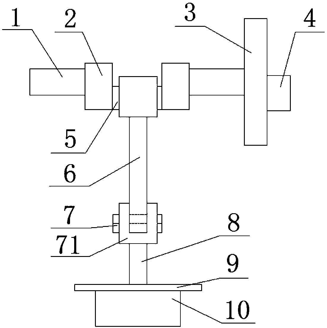
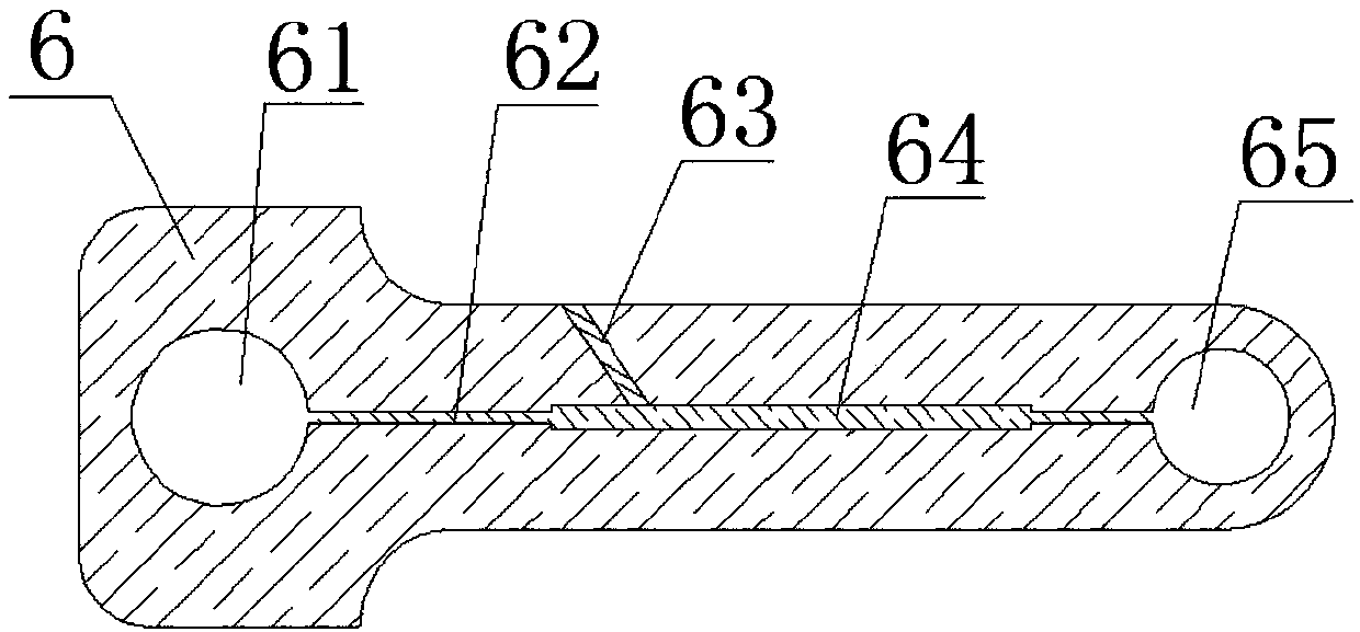
[0014] Such as figure 1 and figure 2 As shown, a crank slider of a mechanical press includes a crank rod 5, a brake 1, a clutch 3, a connecting rod 6, a slider 71, a punch 8 and a die 10, and the connecting rod 6 is provided with a first shaft Holes 61, lubricating passages 62, vent holes 63, lubricating oil chambers 64 and second shaft holes 65; the left end of the connecting rod 6 directly cooperates with the crank rod 5 through the first shaft hole 61, an...


PUM


Abstract

The invention discloses a mechanical press crank slide block comprising a crank rod, a brake, a separation and connection device, a connection rod, a slide block, a male die and a female die. The connection rod is provided with a first shaft hole, a lubricating oil passageway, a vent hole, a lubricating oil cavity and a second shaft hole. The left end of the connection rod is directly matched withthe crank rod through the first shaft hole, and the right end of the connection rod is matched with the slide block through the second shaft hole. The lubricating oil cavity communicates with the outer portion of the connection rod through the vent hole. The lubricating oil cavity communicates with the first shaft hole and the second shaft hole through the lubricating oil passageway. The brake isinstalled on the left side of the crank arm, and the separation and connection device is connected to the right side of the crank arm. The male die and the female die are connected into a whole and are arranged at the bottom of the slide block. The mechanical press crank slide block is small in energy loss, stable in operation and free of impact, and the situation that due to high-speed frequentfriction, the matching position of the connection rod and the crank rod and the matching position of the connection rod and the slide block are damaged is avoided.

Description

technical field [0001] The invention relates to the field of stamping machine parts, in particular to a crank slider of a mechanical press. Background technique [0002] The mechanical press is a forging machine driven by a crank connecting rod or a toggle mechanism, a cam mechanism, and a screw mechanism. It is a machine tool used for pressure processing of materials. Component. Stable work, high working precision, good operating conditions, high productivity, easy to realize mechanization and automation, suitable for working on automatic lines, widely used in industrial machinery presses such as automobiles and ships. The general mechanical press has low processing efficiency, and the clutch and brake are easy to wear, resulting in large energy loss. Contents of the invention [0003] The object of the present invention is to provide a crank slider of a mechanical press, which has simple structure, low energy loss, stable operation without impact, and self-lubrication,...

Claims


Application Information

Patent Timeline
Patent Type & Authority Applications(China)
IPC IPC(8): B30B1/26B30B15/00
CPCB30B1/26B30B15/0088
Inventor 曾素容
Owner 重庆奥阳模具制造有限公司
Features
  • R&D
  • Intellectual Property
  • Life Sciences
  • Materials
  • Tech Scout
  • Unparalleled Data Quality
  • Higher Quality Content
  • 60% Fewer Hallucinations
Learn More