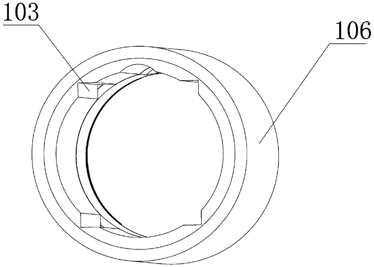
Miniature automatic inflation device

An automatic inflatable and miniature technology, applied in machine/engine, liquid variable capacity machinery, pump control, etc., can solve the problems of large volume of electric pumping equipment, obstacles to the miniaturization of the whole machine structure, and large volume of electric inflatable pump, etc. The effect of easy ergonomics, simple appearance and small footprint

Pending Publication Date: 2020-06-19
苏州贝米科技有限公司
View PDF1 Cites 0 Cited by
  • Summary
  • Abstract
  • Description
  • Claims
  • Application Information

AI Technical Summary

Problems solved by technology

Such electric pumping equipment has a large volume and is inconvenient to carry
The axial direction of most of the motors in the existing electric pumping equipment is perpendicular to the reciprocating motion direction of the piston, so the motor and the cylinder are located on two different axial directions and are distributed at right angles. Correspondingly, the volume of the electric air pump is relatively small. Large, takes up a lot of space, and is not easy to carry around, especially for cycling enthusiasts, portable and easy-to-use pumping equipment is what they need urgently
[0005] Although there are also some relatively small electric pumping equipment, such as the structure disclosed in the application number 2014202418421, the driving structure of this structure uses a gear structure to convert the rotary motion of the motor into the linear movement of the piston. The axis is perpendicular to the axis of the cylinder and is located below the cylinder. In addition, a certain support structure is required to make it self-rotating. Therefore, the area of ​​the corresponding area of ​​the cylinder must be large enough to effectively install the driven gear, which is The inner diameter of the entire cylinder increases, which hinders the further miniaturization of the whole machine structure
[0006] In addition, the volume of the air cavity formed between the piston rod and the piston barrel is small, the amount of gas that can be charged into the object to be inflated by the piston reciprocating once is small, and the inflation efficiency is low

Method used


Image

  • Miniature automatic inflation device
  • Miniature automatic inflation device
  • Miniature automatic inflation device

Examples


Embodiment Construction

[0041] Objects, advantages and features of the present invention will be illustrated and explained by the following non-limiting description of preferred embodiments. These embodiments are only typical examples of applying the technical solutions of the present invention, and all technical solutions formed by adopting equivalent replacements or equivalent transformations fall within the protection scope of the present invention.

[0042] In the description of the scheme, it should be noted that the terms "center", "upper", "lower", "left", "right", "front", "rear", "vertical", "horizontal", " The orientation or positional relationship indicated by "inner", "outer", etc. is based on the orientation or positional relationship shown in the drawings, and is only for the convenience of description and simplification of description, rather than indicating or implying that the device or element referred to must have a specific orientation , constructed and operated in a particular or...


PUM

PropertyMeasurementUnit
Outer diameteraaaaaaaaaa
Lengthaaaaaaaaaa

Abstract

The invention discloses a miniature automatic inflation device. The miniature automatic inflation device comprises a shell, a motor and a piston; the shell is provided with an air inlet and an air outlet, the motor is arranged in the shell and used for providing power, the piston is telescopically arranged in the shell in a reciprocating manner and is driven by the motor, and a cavity is formed between the piston and the shell, the piston is driven by an output shaft which is coaxial with the piston and driven by the motor to rotate forwards and backwards in a staggered mode to stretch and retract in a reciprocating mode, and the piston is limited by an anti-torsion structure and cannot rotate relative to the shell. According to the scheme, through forward and reverse rotation of the motor, a ball screw driving structure and a thread driving structure are combined, a rolling connection or sliding connection structure between a spiral groove and the piston is adopted, an effective implementation mode is provided for a small-size driving structure, the structure is small in occupied space, favorable conditions are created for miniaturization of the whole machine, and the miniature automatic inflation device provides possibility for carrying about

Description

technical field [0001] The invention relates to the field of inflatable equipment, in particular to a miniature automatic inflator. Background technique [0002] Inflatable equipment is a special equipment for inflating airbags, balloons, tires and other products, and is closely related to people's daily life. [0003] There are many types of pumping equipment now, mainly manual pumping equipment and electric pumping equipment. In order to achieve the portability function of the manual pumping equipment, the volume of the pumping equipment is reduced as much as possible in terms of the form of the pumping equipment. However, due to the reduced volume of the manual inflator, its inflatable cavity is small. When inflating, it is difficult for the user to hold the manual inflator to apply force to inflate, and the volume of the gas in one charge is also very small. strenuous. [0004] And all kinds of electric pumping equipment, use the motor etc. as the power source to driv...

Claims


Application Information

Patent Timeline
IPC IPC(8): F04B35/04F04B39/12F04B39/00F04B49/06
CPCF04B35/04F04B39/0005F04B39/0022F04B39/121F04B39/122F04B39/125F04B49/06
Inventor 刘良兵赵殿虎
Owner 苏州贝米科技有限公司
Why Eureka
Try Eureka